History of the Atlantic Cable & Undersea Communications
from the first submarine cable of 1850 to the worldwide fiber optic network
Early Cable Instruments
|
History of the Atlantic Cable & Undersea Communications |
Early Cable Instruments | |
Early Cable Instruments The first practical electric telegraph systems went into service in England in 1839 and in the United States in 1844. Only a few years later, by the late 1840s, enterprising promoters in Britain were proposing undersea cables across the English Channel to France, and the first working cable was operational on that route in 1851. And just three years after that, in 1854, in a bold leap of optimism Cyrus Field decided that the Atlantic could be bridged by a 2000-mile cable from Ireland to Newfoundland, almost a hundred times longer than any yet laid. The short cables laid up until then could be worked by equipment similar to that used on landlines, with sensitive galvanometers as the receiving instruments. But long cables presented problems several orders of magnitude more difficult. Firstly, the great length of the conductor, combined with the low-purity copper available in the 1850s, meant that the signal was heavily attenuated and could barely cause a standard galvanometer needle to twitch, much less show an intelligible signal. And secondly, the very high capacitance of long underwater lines resulted in a time lag and smearing of the signal as the cable slowly charged and discharged with each dot or dash, to the point where individual code elements could not be distinguished at the receiving end. I’ll have more to say later about the capacitance problem, but the initial concern of the cable electricians was to get a readable signal. Now of course there were two ways they could have done this. One was to increase the voltage of the transmitted signal; the other was to improve the sensitivity of the receiving instruments. Enter Edward Orange Wildman Whitehouse, and William Thomson (later Lord Kelvin). Thomson came from a rigorous scientific background, technically inclined from an early age and educated at Cambridge University, where he graduated with high honours in 1845, then took up a professorship at Glasgow University. His attention was brought to the problem of signals in long cables in 1854, and he then performed a theoretical analysis of the electrical performance of undersea cables in which he determined that the strength of the signal followed an inverse square law. He made some suggestions for the optimum design of long cables in a paper published in 1855. Meanwhile Whitehouse, a surgeon by profession, had caught the telegraphy bug in the early 1850s, abandoned his medical practice, and started experimenting on signal transmission. He took out several patents in the field, the first in 1853. He disagreed with Thomson’s conclusions after experimenting on lengths of the Mediterranean cable in 1855 before it was laid, and presented results which he said backed his claims, although Thomson rebutted this. All this was without the benefit of any rigorous theory on Whitehouse’s part, as was common in those early days of electrical technology. Nonetheless, Whitehouse was appointed Electrician (i.e. Chief Engineer) to the Atlantic Telegraph Company, and was given responsibility for the testing and working of the Atlantic cable. Whitehouse’s experiments had led him to believe that high voltages were the answer to the poor conductivity of long cables. He had built and tested a number of large induction coils operated by banks of batteries, and convinced the company that using a high voltage coil would allow speedy working of the Atlantic cable, and could even operate a printing instrument at the receiving end.
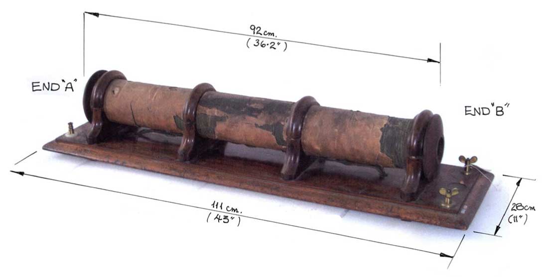
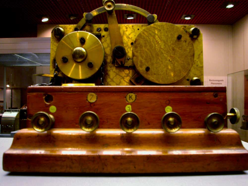
This induction coil, made by Whitehouse in the 1850s and now in the reserve collection of the Science Museum in London, is an amazing 36 inches long. It is believed to be similar to the one that Whitehouse used to work the Atlantic cable in 1858 – that one being even bigger, at five feet long, and generating pulses of up to 2000 volts. Using this extremely large and poweful coil he was able to read signals through the 1858 cable using a standard galvanometer made by the W.T. Henley Telegraph Works Company.
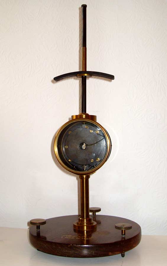
William Thomson, meanwhile, had no official standing with the Atlantic Telegraph Company, but was asked to consult on various technical matters. Showing considerable business acumen for an academic, he had already started taking out patents on technology he thought would be useful in the cable industry, a policy he continued throughout his career, making him a very wealthy man. He took the opposite approach from Whitehouse, and designed a much more sensitive version of the standard galvanometer, using a tiny mirror mounted on the coil to magnify the very small movements of the meter when used on a long cable.
Thomson patented his mirror galvanometer in 1858, and tested it prior to the 1858 Atlantic cable expedition, but Whitehouse, in his official capacity as Electrician of the project, insisted on using his high voltage equipment on the Atlantic cable. For a short time he was able to read signals sent from Newfoundland to Ireland using the standard galvanometer, but the cable soon began experiencing problems and Whitehouse had to use the mirror galvanometer to read anything at all, although he did not mention this in his reports to the directors. Thomson's mirror galvanometer was also used on the USS Niagara to read test signals sent over the cable while it was being laid.
After the early failure of the 1858 cable, attributed to Whitehouse’s extremely high voltages breaking down the insulation in some sections of the cable which had deteriorated in storage prior to being laid, the use of induction coils was completely discredited. Thomson’s mirror galvanometer became the standard receiving instrument, allowing long cables to be worked using just a few volts at the sending end.
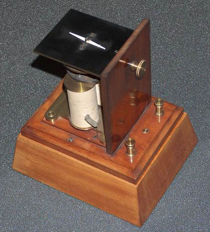
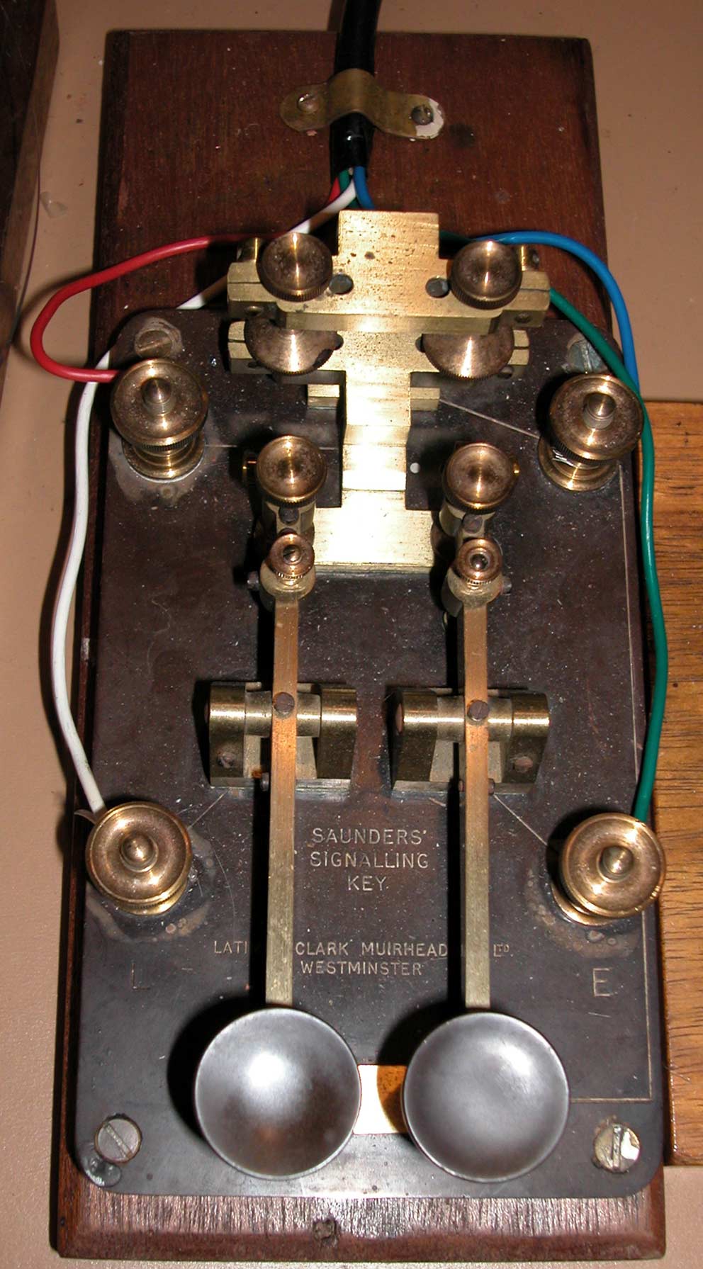
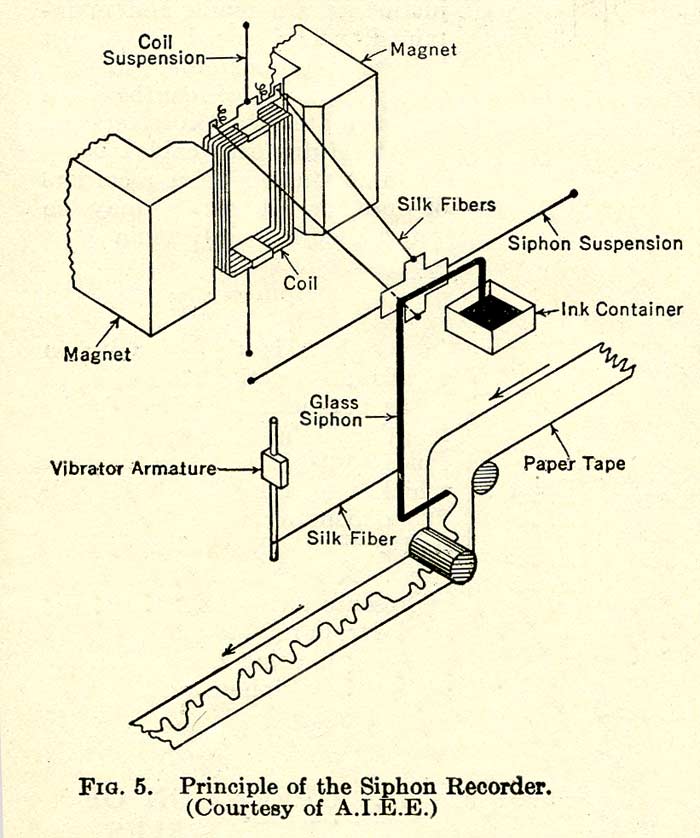
The problem of capacitance smearing the signal had also been addressed, and this was resolved at least sufficiently to give a working speed of a few words a minute by using positive and negative voltages to represent dots and dashes, instead of same-voltage pulses of different lengths. By grounding the cable between each transmitted pulse, the components of each character could be read, with some difficulty, at the receiving end. The use of positive and negative voltages required a special key with two levers, fitted with contacts to send the appropriate polarity and to ground the cable in between each pulse. This became known as a cable key, and the design remained in use throughout the life of telegraph cables, well into the 1950s. The disadvantage of the mirror galvanometer was that it required two operators, one with a steady eye to read and call off the signal, the other to write down the characters received. Thomson again came to the rescue with his siphon recorder, effectively an ink-jet printer, which he patented in 1867 and licensed to the cable companies. This used the tiny movements of the galvanometer coil to operate a fine glass tube immersed in a trough of ink at one end, and poised just above a moving paper tape at the other.
The ink was siphoned up through the glass tube and sprayed onto the paper tape by an electrostatic charge generated by a device called a “mouse mill”. Thomson’s siphon recorder came into general use in the 1870s. It allowed unattended recording of the received signal, and also created a permanent record of each message on the paper tape, or slip, which after transcription for forwarding or printing could be filed in case of later queries. Like the cable key, the siphon recorder remained in use as the standard receiving instrument throughout the life of telegraph cables. On later versions the siphon tube contacted the paper and a mechanical vibrator was used to reduce the friction. Because of the high capital cost of laying ocean cables, the operating companies needed to maximize the message throughput in order to obtain the maximum return on their investment. Hand keying was too slow, so the next development was automatic transmitters. Like the siphon recorder, these operated on paper tape, but for transmitting the tape was punched with a series of timing holes down its center, on either side of which were holes representing positive and negative signals, or dots and dashes. The tape was fed into an automatic transmitter which by means of the timing track moved the tape at a constant rate and translated the holes into the appropriate voltages to be transmitted over the cable. Charles Wheatstone, the originator of telegraphy in Britain, patented the first automatic transmitter for landline telegraphy in 1858, but it was not adapted to cable use until somewhat later.
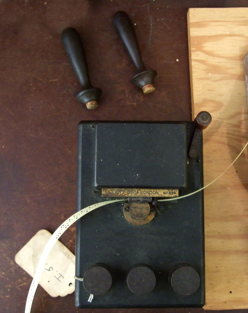
To make the holes for outgoing messages a number of instruments were devised. First was the hand punch or mallet perforator(below, left). This was operated by striking either lever with a small mallet, causing either a dot-hole or dash-hole to be punched in the message tape.
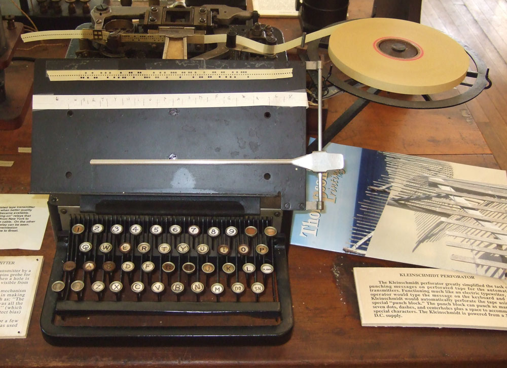
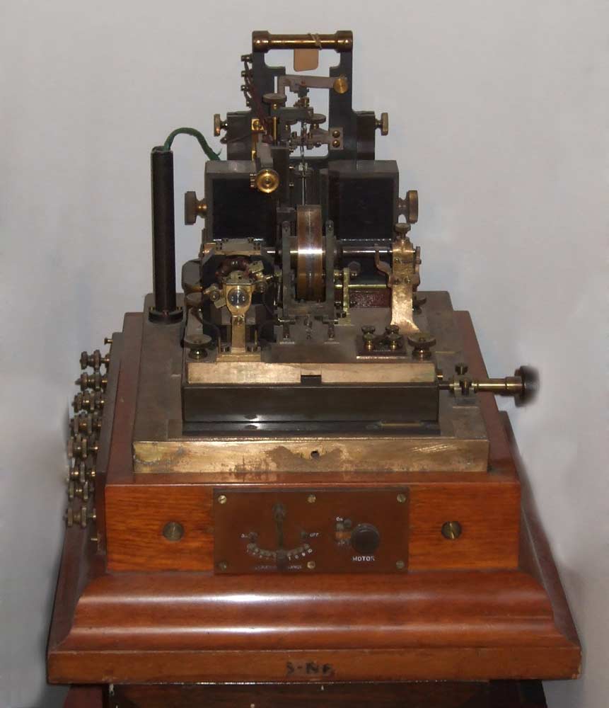
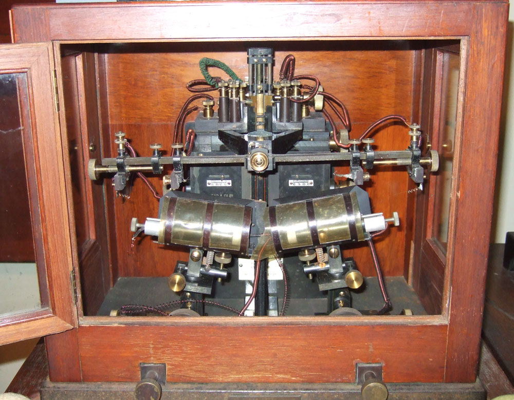
After the invention of the typewriter the machine was eventually adapted for punching tape. The Kleinschmidt perforator, introduced in 1910 (above, right), was used in many cable stations, a predecessor of the Teletype machine. The last remaining problem was the onward transmission of the tiny signals received over the cable. The signals could only be received using a siphon recorder, and there was no way to relay messages onto another cable or a land line without re-keying—a time-consuming and error-prone procedure. Before the invention and further development of the vacuum tube there was no way to amplify signals electronically, so the ever-ingenious cable engineers devised various electromechanical relays and amplifiers, or “magnifiers” as they were called. Two instruments commonly used on long cable circuits worldwide were the Brown Drum Relay and the Heurtley Magnifier, both invented in the early 1900s. Like the siphon recorder, these were very sensitive instruments mounted on heavy bases (the Brown Drum Relay weighs over a hundred pounds), and they were generally installed on steel supports to a concrete foundation under the cable station, independent of the building structure.
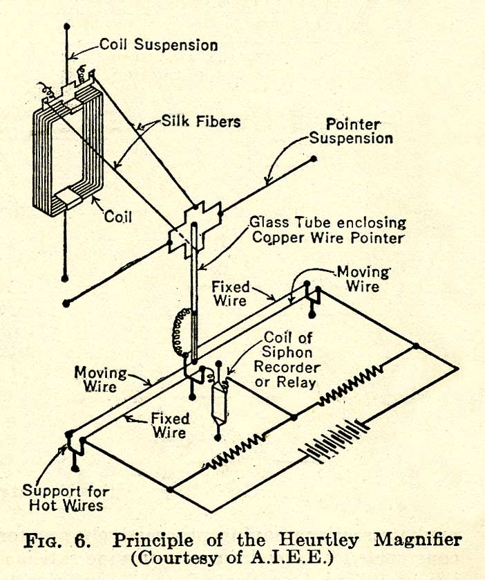
The Brown Drum Relay again used the basic principle of the mirror galvanometer and siphon recorder, but this time the galvanometer coil carried a very light contact wire, which moved left and right according to the signal polarity. The end of the wire rested on a spinning drum, about three inches in diameter, which had an insulated center section with silver contact surfaces on both sides. The effect of spinning the drum was to greatly reduce the friction on the tip of the contact wire, allowing the very small signal currents to move it freely from side to side. As the tip of the wire contacted either the left or right silver surface, this switched a higher voltage signal which could then be relayed onto another circuit. The Heurtley Magnifier was even more ingenious. The principle here was that of the Wheatstone bridge. It relied on the signal currents moving platinum wires in and out of an air stream, which allowed the wires to heat up when out of the air stream and cool down when in it. The resulting changes in resistance unbalanced the Wheatstone bridge, creating much higher currents in the other arms, which could then be used to relay the signal.
The final development in telegraph cable signalling was electronic amplification, starting in the late 1930s. But despite this availability of vacuum tube equipment for undersea circuits, many of the electro-mechanical instruments continued in use at remote cable stations worldwide for another twenty years or more, as they were reliable and familiar. With the introduction of repeatered submarine telephone cables across the Atlantic in 1956, voice circuits on these cables were used to carry multiple telegraph channels, and by the early 1960s all the telegraph cables had been taken out of service and the stations closed.
While the cable repeater was a major step forward, leading to a rapid expansion of the cable network from the mid-1950s, and eventually to today's fiber optic network, somehow this modern equipment just doesn’t have the appeal of all those early mahogany and brass instruments... |
|
Last revised: 27 March, 2011 |
|