History of the Atlantic Cable & Undersea Communications
from the first submarine cable of 1850 to the worldwide fiber optic network
Wildman Whitehouse Patent 2,027 of 1860
|
History of the Atlantic Cable & Undersea Communications |
Wildman Whitehouse Patent 2,027 of 1860 |
|
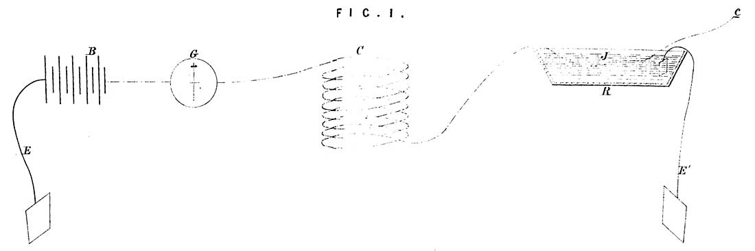
SPECIFICATION in pursuance of the conditions of the Letters Patent, filed by the said Edward Orange Wildman Whitehouse in the Great Seal Patent Office on the 23rd February 1861. NOW KNOW YE, that I, the said Edward Orange Wildman Whitehouse, do hereby declare the nature of my said Invention, and in what manner the same is to be performed, to be particularly described and ascertained in and by the following statement, reference being had to the accompanying Drawings and to the letters and figures marked thereon, that is to say:- In the testing of insulated conductors for submarine electric telegraph cables, the mode of procedure has hitherto been to place battery and galvanometer in circuit between the earth and one end of the cable, the bulk of the cable being immersed in a tank in contact with earth, while the other end is free and insulated. The amount of current passing through the instrument has been regarded as the measure of the “loss” by defective insulation. Or, the current thus passing has been compared with that passing through a known and measurable resistance by means of some rhaeostatic arrangement, and thus the resistance of the cable, as it is termed, has been determined. During the manufacture of submarine electric telegraph cables, as mile after mile is added to the length previously made, great care has always been required to make a sound “joint,” as it is called, in the insulating covering at the point of junction; and it has been the invariable practice, I believe, after such joint has been made and before it is allowed to be covered with the outer iron wires of the cable to test it by immersion in a pail or trough of water, in connexion with the earth, careful observation being made at the time to detect if any increase become apparent in the current entering the cable. So long as the entire length of cable under examination does not exceed a few miles, the detection of a very slight degree of fault at a “joint” is quite possible, and even comparatively easy; but on examining lengths of cable approaching to or exceeding one hundred miles, where the minute increase of loss due to the joint is merged in the largeness of the total amount of leakage, it becomes impossible with the utmost care and delicacy in this mode of testing, to determine whether the joint in question (which may be eight or ten inches in length) give fifty or one hundred times, or even one thousand times as much loss as au equal length of perfect cable should do. A degree of imperfection which must thus inevitably pass undetected may ultimately most seriously endanger the safety of the whole cable. This is more particularly the case in long cables, where at the same time the greatest amount of property is at stake; for it is demonstrable that while on the one hand the longer the cable the greater is the necessity for the highest attainable degree of insulation, on the other, it is precisely under these conditions that it has been heretofore impossible, by the accredited mode of testing, to detect degrees of imperfection at the joint, which yet would sooner or later entail the certain destruction of the cable. By the improvements now to be described, it becomes as easy to detect and measure the slightest appreciable loss upon a joint made in a cable one thousand miles in length, as it would be if the joint in question were a short specimen detached for the purpose of testing. An examination of the simple plan of the circuits annexed, will show that the principle of my Invention is, to separate the current lost at the joint from the sum of that lost upon the rest of the cable, and to examine it by the use of a separate instrument. This is most simply effected by insulating the trough or reservoir into which the joint is plunged for testing and conveying the current (so caught) through a very sensitive galvanometer to earth. Figure 1 of the accompanying Sheet of Drawings represents a Diagram of the circuits in the old mode of testing. B is the battery, one pole being connected with the earth by the wire and earth plate E, the other pole being attached to the galvanometer G, through which the current passes to the cable C, the joint J of which to be tested is immersed in the reservoir R, which is connected with earth by an earth plate and wire E1. c is the free insulated end of the cable.
Figure 2 annexed, is a plan of the circuit for the simplest form of testing, adopting this improved principle; B, the battery; C, the cable in contact with earth; c, the free and insulated end of the cable ; E, E1, earth wires; R, reservoir containing water, mercury, or other conducting fluid; J, joint; G, galvanometer.
Figure 3 is a plan of the circuits, inverting the direction of the current, which will now pass from the insulated reservoir to the cable through the joint, and thence out by the conductor through a galvanometer to earth.
Figure 4 is a plan of the circuits in which the earth wires may be joined across direct from the insulated reservoir through the galvanometer to the battery, instead of being carried to earth plates, as usual. In all these the principle is, that of testing the loss at the joint, or part examined, separately from that existing on the rest of the cable.
If it be desired to test in other well known ways, as for example, by the differential method, by resistance cables or rhaeostats, by Wheatstone's bridge, or by electric tension, or in any other method, the plan of the circuit will, of course, quoad hoc, be correspondingly altered in detail, as will be well understood by electricians; but whatever be the mode adopted, the improvement in which my Invention consists, and which is equally applicable to all, is essentially the examination of the loss (or escape of electricity) at the suspected part as it were separately from the rest of the cable by such arrangement of the circuit and instruments as shall permit of such examination apart from the aggregate of the loss existing upon the rest of the cable. A less perfect mode of applying the same principle, but still a manifest improvement upon the present mode of testing joints, would be by the use of a wetted cloth or damp sand, or some similar material with which to surround the joint, this would be then laid upon an insulated slab instead of the trough, the connexions and circuit remaining as before. In witness whereof, I, the said Edward Orange Wildman Whitehouse, have hereunto set my hand and seal, this Twenty-third day of February, One thousand eight hundred and sixty-one. Return to the Wildman Whitehouse patents page |
|
Last revised: 4 June, 2010 |
|