History of the Atlantic Cable & Undersea Communications
from the first submarine cable of 1850 to the worldwide fiber optic network
Repairs - Making the Splice
|
History of the Atlantic Cable & Undersea Communications |
Repairs - Making the Splice |
|
|
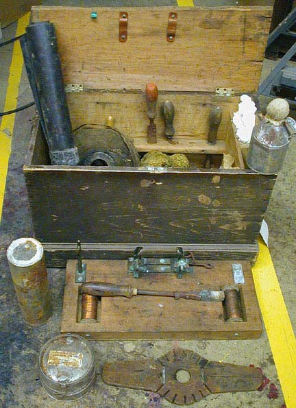
From Submarine Cable Laying and Repairing by H.D. Wilkinson. London: ‘The Electrician” Printing and Publishing Company. First published 1896. This text is taken from the second edition, 1908. See also this page on a jointing instructional case issued by the Telegraph Construction & Maintenance Company to be carried on board its cableships. We will now turn our attention to the making of the cable joint and splice. Joint in Core. Before the work of jointing and splicing is commenced the end of the new piece of cable to be joined on is brought up into position for paying out, so that everything will be ready to pay out as soon as the splice is completed. It is not usual to fit repairing-vessels with a separate brake gear aft for paying out, as in the large cable-laying steamers, the spare drum and brake on the picking-up gear being available for this purpose. In the tank from which cable is to be paid out, the end is passed up through the crinoline, and out through the bellmouth above the tank, thence forward to the hauling-off sheave and drum, round which it is wound four or five times. If it is intended to pay out from the bows the end is then in position for splicing ; but if paying out is to be done over the stern, the end is taken aft, passed under the pulley of dynamometer at that end of ship, over stem sheave, round outside ship to bows, and back inboard again over one of bow sheaves The end is then stoppered, about 15 fathoms of slack being left on deck for splicing. The two ends to be spliced now come inboard side by side over the bow sheaves, and when spliced together the bight so formed is slipped overboard, and cable at once takes its proper place for paying out over the stern. Of course when the end is taken forward to pay out over bows after splicing, there is no bight to slip.
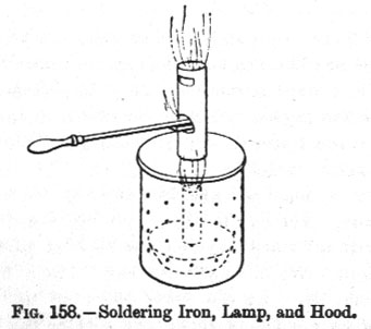
The cable having been got into position, the two ends are brought up together for jointing. On one end, which we will call the left end, for distinction, the sheathing wires are unlaid for a length of about 60ft., and all the exposed core out away except about 4ft. On the other end - the right end - the sheathing wires are cut or opened out about 3ft. back and the ends lashed round to keep them in place. This leaves 3ft. of core exposed for convenience of jointing. The core ends on both sides are then prepared by stripping off the insulation with a sharp knife to a distance of 1½in., care being taken not to nick the wires. The strand is then opened out, each of the seven wires being scraped and cleaned bright with glass-paper and then with a pair of pliers the whole twisted back again into a strand as before. Each end is then soldered, and for this purpose the soldering-bit, spirit-lamp and hood, shown in Fig. 158, are used.
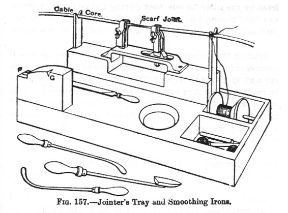
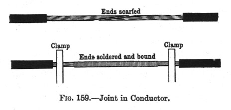
With a hood of this kind over the lamp a good draught of air passes through the small holes and out at the top, while the flame itself cannot be blown out by the wind. If the wind is vary strong an impromptu shelter of sail or awning cloth is put up round the jointer. The soldering-bit is pushed into a hole cut in the chimney of the hood for the purpose, where it holds itself in the hottest part of the flame, and in this way two bits can be kept going and no time lost. Either powdered resin or Baker’s fluid is used as a flux. First brush the copper strand with the flux and then hold the soldering-bit (previously tinned) in the right hand, narrow face upper-most, and melt a blob of solder on to it. Put this blob under the wire, holding the latter in the left hand and pressing the iron and the wire together. A little flux is now applied and, immediately the solder takes, jerk the bolt away, to carry away excess solder, otherwise it will have to be filed off. By doing this quickly the iron has not time to heat the G. P. insulation on the wire. Then snip a good 1/16 in. off the end with pliers. The end is then filed down taper on one side, as shown in Fig. 159, for a scarf joint, so that the ends when laid together exactly fit and make no increase in the size of the conductor.
On the jointer’s tray, illustrated in Fig. 157, there is a block of wood on the left side, in which is cut a niche, G. This niche answers the purpose of a gauge to assist in filing both ends equally to the same taper. The end is laid in the niche and filed away till flush with the block, making the tapered part about an inch in length. While filing, the end is held in a pair of flat-nosed pliers gripping the strand close up to the percha. The ends are next laid in turn on the side of the block at F, and the rough corners left by the solder filed off, after which they are surfaced over with emery cloth. At this stage the ends are solid, fitting truly together and presenting a bright, silvery appearance. They are now held together in the clamps on the jointer’s tray (Fig. 157), which grip the conductors close to where the insulation is cut away. One of these clamps is movable along a slot, so that when the wires are properly held they can be brought close together with little pressure, by moving up this clamp as required, and then fixing it by screwing up the nut underneath. The joint is now bound round with fine copper binding wire. A length of this wire is unwound from the reel in the jointer’s tray, brightened up with No. 0 emery cloth, and then doubled in three or four like a flat band composed of three or four wires. So held, it is bound tightly round the joint in one direction, say from left to right, and to within a quarter of an inch of the clamps on each aide. The turns in this first binding are well apart, the object being only to hold the joint together for soldering. The whole is then soldered over, the solder running in between the binding wires, and making a neat solid joint. The binding wire wrapping is then removed, and a second binding laid on. In this the turns are quite close together and it is laid on in the middle part only. After soldering this on, a third wrapping is laid on, this time in the opposite direction - right to left - and close up to the clamps on each side. This wrapping is soldered only at the extreme ends for about a quarter of an inch from the clamps, the object being that in case the cable is subsequently fractured at the joint the wire not being soldered will not break with the cable, but open out and maintain continuity. Finally, the ends of the binding wire are snipped off, and a six-inch smooth file run over the soldered parts to take off any projecting points and make the joint perfectly regular all the way along. So far there will not be found much difficulty in jointing after a little practice in keeping a nice clean tinned end on the bit. There is considerably more practice required in the succeeding operation of making the joint in the insulation, the difficulty being at first to keep air bubbles excluded from the material while hot, and to finish with the jointed conductor perfectly central in its insulating covering. Should there be any air bubbles imprisoned in the joint they are sure to be the cause of ruptures in the insulation sooner or later in consequence of the great pressure at the bottom of the sea. This pressure amounts to one ton and a quarter per square inch for every 1,000 fathoms depth; and when the cable is sunk and subject to this pressure any places where air is imprisoned are liable to burst open and cause serious faults. The soldering fluid is first cleaned off the joint by rubbing with a clean bit of rag soaked in wood naphtha, and after drying it the first coat of Chatterton’s compound is laid on. The end of a stick of this compound is heated in the spirit lamp flame, care being taken not to keep it in the flame long enough to burn, or there will be trouble from air-holes. The bare part of the joint is also heated very slightly to receive the coat. The stick of compound is then worked along over the joint as well as possible to cover every part, and is followed up by a smoothing iron. This is a smooth iron tool, curved at the end (Fig. 157) which, when heated and worked over the coating of compound, spreads it out in any desired way; thus where the compound is too heavily laid on in places it can be worked down into cavities so as to make it everywhere of the same depth. Any imprisoned air is worked out by this tool, and the coating finally smoothed round evenly by the finger and thumb, first wetted, so as not to adhere to the material. The gutta-percha covering of the core on each side of the joint is now dealt with, the spirit flame being held underneath while the core is turned round backwards and forwards. The ends of the insulation, after warming, are then drawn together till they are about ½in. apart, and one end is drawn down to a point, while the other is drawn over it (Fig. 160) thus completely enveloping the joint in the same material as covers the conductors on each side. The end so left is further heated and smoothed down. A second layer of compound is now spread over the percha, precisely as before. Some sheet gutta percha is now taken, and a square piece about 3in. wide cut off. This is heated over the flame, and a strip cut off, about 1½in. wide, which is then taken, and one end laid against the core underneath at A (Fig. 160) the other end hanging down. From this point the strip is pressed upwards against the core by the fingers working along from A to B, and is then heated again and pressed all round the core till the ends meet at the top, as in the figure. The reason for this careful treatment is to make sure there are no air bubbles imprisoned by commencing at one end and squeezing the strip against the core in every part till the whole is covered. When completely pressed all round, the two sides of the strip stick up close together, and are nipped together by the finger and thumb all along so as to form a seam. The seam is then cropped close to the core with a pair of scissors, and the ends, which now butt, squeezed together. This coat is followed by another piece of G.P. sheet put on in the same way, but with the full part of the strip over the seam of the last. This second coat is a little more than twice the length of the first - that is, about 8in. The joint is then completed by working down smooth the ends of these strips at A and B, so as to taper off gradually on to the core on either side, and finishing with Chatterton well smoothed over by rubbing it with the hands well moistened. A well-made joint is, when finished, from 6in. to 9in. long, and not much larger in diameter than the adjacent core.
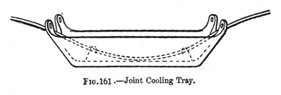
The beginner should experiment on short lengths of core, and test his joint by comparing its insulation with a few feet of perfect core by Clark’s accumulation method, being careful to dry very thoroughly that part of the core which is not immersed. Then, if sound electrically, he should slice off half of the insulating covering with a sharp knife, so as to lay the joint bare along one side, and notice how near the jointed conductor lies in the centre of the insulating covering. To get the joint central a good deal depends upon working the hands evenly over every part of the coatings as they are put on. In the first attempts the failures usually are too little insulation on one side and too much on the other, the separate layers distinctly visible in section showing that they have not been united by the proper application of heat and pressure, and too great bulkiness of the finished joint due to insufficient working of the material by the fingers and smoothing iron. Before anything more can be done the joint must be thoroughly cooled, and for this purpose it is held down in a gutta-percha tray (Fig. 161) containing either a diluted mixture of muriate of ammonia and saltpetre, or a few lumps of ice in water.
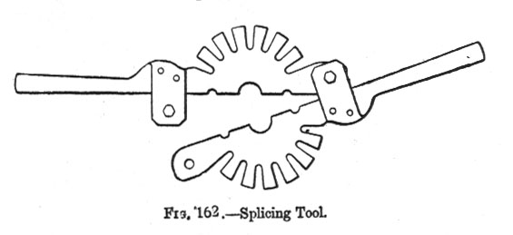
The proportions of this cooling mixture are given in Munro and Jamieson’s "Pocket Book of Electrical Rules and Tables" as five parts of muriate of ammonia to five parts of saltpetre and 16 parts of water. The joint is held down in the cooling mixture by two hooks at the bottom of the tray, and remains in for 15 or 20 minutes. The tray is entirely of gutta-percha and provided with four lugs for suspending, thus thoroughly insulating it when required for use during tests of joints in short lengths spliced up on board. Meanwhile the further end of the new piece of cable in tank (on the near end of which the joint has just been made) is connected to the testing-room, and remains so connected, in order to test the cable as it is payed out, and communicate occasionally with the shore. From this end, when the joint is cool, a test is taken through the united cables, the end on shore being free. The insulation of the seaward end, and that of the new piece spliced on being known, it is easily calculate what the two jointed together ought to give; and if the joint is not perfect the resultant insulation will be lower than this. But jointers very rarely fail to make a perfect joint, having served their time in the factory, where joints occur on every two miles of core manufactured, and the men being chosen as reliable for sea work. Cable Splice. Before the splice in the sheathing wires is made, the core is served with a layer of tape or loose spun threads, over which is laid a serving of brass tape, followed by jute or Russian hemp, bound at intervals with seizings of fine yarn, The splice is then begun on the right side, and when the sheathing wires have not been cut but opened out, the wires are relaid close together by means of the splicing tool (Fig. 162).
This tool is made in steel plate, with notches in the form of two half circles, in which the sheathing wires are placed. The tool is opened in the middle to set it in position across the cable and put the wires in order in their respective notches, and is then closed up and fastened by a small set screw and nut. It is then worked round by the handles in the direction of the lay, and in this manner the wires are forced round the cable in their proper places spirally, exactly similar to the other part of the cable. Little by little as the tool is worked round it is pushed forward along the cable; for example, in the deep-sea type the lay of the sheathing wires being ten inches, the tool would be pushed forward a distance of ten inches during every complete turn it makes round cable. With steel wires the work is much more difficult than with galvanised iron, as the spring of the steel exerts a considerable resisting force to the twist. As the tool is worked along it is followed up in places by seizings of yarn round the cable to keep it from springing back. In Fig.163 this tool is shown in position as used, the sketch representing the operation as nearly completed on the right wires. As soon as the tool is worked round to the end of the wire - that is, to where the left wires are unlaid - a final seizing is put on about 4in. from the end, and the tool removed. With a hand cutting tool the ends are then snipped off perfectly equal in length. The left wires are now taken in turn, and every two wires alternately if small, or every one alternately if large wires, are snipped off short, so as to exactly butt the ends of the right wires. The alternate pairs of wires remaining on the left side, which are all about 60ft. in length, are then laid in turn on the right side, corresponding pairs of right wires being unlaid to receive them. Take, for instance, one such pair. It is first of all noticed which pair of right wires lies in the same lay as the pair of left wires we are considering. This pair of right wires is then unlaid for some distance, say 30ft., and the corresponding pair of left wires threaded in under the seizings, so as to lay in the place thus vacated for them. One wire of the left pair, and one wire of the right pair, which lie in the same lay, are then snipped off so that their ends lie exactly butt together. The single right wire that remains is then further unlaid, and is followed up by the remaining left wire, which is laid in the place vacated by it. This is continued for about 30ft. further, when the ends of both wires are snipped, so as to lie butt together. The next alternate pair of wires is then taken and treated in the same manner ; this time the wires being cut at shorter distances than the above, so that the butted ends do not all lie near together; The next pair follows, and the wires are cut at still shorter distances than the preceding ones, and so on to the last pair; the procedure in this respect being similar to that in manufacture, when no weld in any of the sheathing wires is allowed to be nearer than ten feet to any other weld in the same or any other wire. With the left wires 60ft. long as given above, and with 16 sheathing wires as shown in the illustration, there would be eight wires carried over on to the right side, and the butt joints between these and the right wires would be at distances of nearly 8ft. apart.
The appearance of the splice so made is represented in Fig. 164, where the left wires are shaded, so that their course can be traced and understood. Necessarily, in the sketch, for want of room, the splice is shown much shorter in length relatively to the size of cable and sheathing wires than it should be, but it serves the purpose of making the manner of splicing understood. In splices made at the factory between very different types of cable such as the deep-sea and intermediate portions, the sheathing wires of the larger cable are tapered down to the size of the smaller. Apart from the great length of the cable splice, so made for the purpose of distributing the strain, it will be noticed that it differs from the sailor’s rope splice, in which he remembers he must
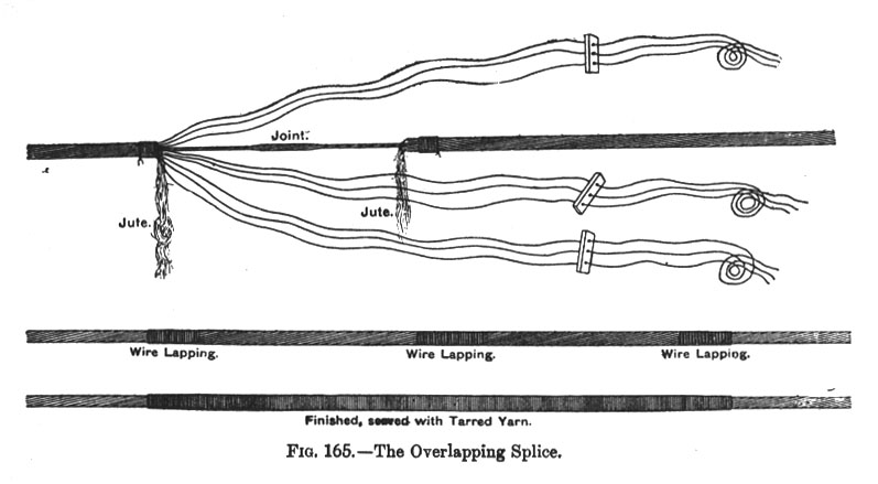
Again, it will be noticed that the joint in the core is covered by the pairs of right and left wires laid together, and is some distance away from the place where the alternate pairs butt so that the joint is well protected mechanically. Over all butts are wrapped seizings of soft iron wire. Another method, known as the overlapping splice, is much in use on account of taking less time to make. For this splice the sheathing wires on one end, which we may call the left wires, are opened out for a length of about 6 fathoms and the core so exposed out away so as to leave only about 3ft. or 4ft. for jointing. The sheathing wires on the other side - the right wires - are then cut off at a distance of about 3ft. from the end, the ends being bound round with a piece of twine or yarn to prevent them opening out. This leaves 3ft. of core exposed on this side. The joint in the core is then made as previously described, and the jute serving, of which a sufficient length has been retained on the cable, is wrapped round it and the bare part of core. The splice between the sheathing wires is now made in the following way. The left wires are taken and divided for convenience in handling into bunches of three or four wires each, and in order to keep them always in the same position abreast of each other the ends of each bunch are given a twist or threaded through holes in small wood cleats, and then twisted (Fig. 165).
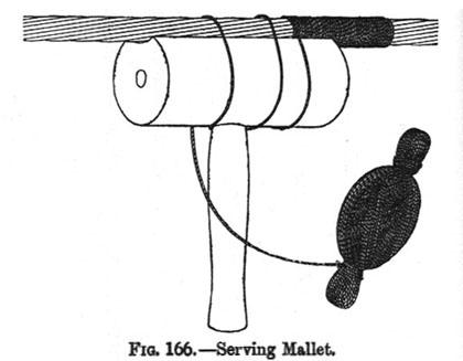
This also gives something to lay hold of and pull on while laying the wires. The ends of the bunches are now taken in hand, and the wires laid spirally over the jute, all the wires coming properly abreast in their right positions. This first covers the joint and core, and has to be done gently until the wires are laid as far as the ends of the right wires. Then, with the assistance of the splicing tool, the wires are overlapped firmly over the sheathing of the other end, and as this proceeds soft iron wire is bound round at intervals to keep the wires in place. The splice is also tapered off by cutting away the ends of the wires at different lengths, and the whole is then served over with tarred yarn by means of serving mallets. This gives the splice a neat finish, and further increases the adhesion between the sheathings. The sketch represents, first, the wires opened out ready to make the splice; second, the overlap as finished, with wire serving at intervals; and third, the finished splice, yarn served. Splices are usually from 6 to 10 fathoms in length, the shorter splices being for types used in shallow water, and therefore not exposed to much strain. It is found in some types that when the wires are of iron they can be laid quite as firmly and well by hand without the aid of the splicing tool, and this is often done ; but in types having sheathing wires of stiff springy steel, the work is much facilitated by the tool. The overlapping splice just described is most often made when the two ends of cable are of different types, or, though of the same type, when they differ in lay. The wires on the left are not picked out in alternate pairs to leave spaces in which to lay the right wires. While the method of picking out and laying in of wires makes a neater job and binds the wires together better, it cannot be done when the cables are of different types or lay, and the overlapping splice has proved thoroughly reliable when made in sufficient length to suit the type of cable, and it takes less time to make than the method first described. It now only remains to cover the whole with a serving of tarred yarn. For this purpose the serving mallet shown in Fig. 166 has long been in use.
The mallet is represented in the sketch in position for serving, one man turning the mallet round by the handle while his mate follows round with the ball of yarn. Pairs of men are stationed along the splice, who commence serving at different points, and continue till they finish where their neighbours began, so covering the whole. The course of the yarn from the ball round the body and handle of the mallet to the cable is shown clearly in the sketch. By the half-turn taken round the root of the handle, the round turns over cable and mallet are in opposite directions, which causes sufficient check on the yarn to render it taut on the cable. An improved serving mallet has been introduced by Mr. F. R. Lucas, of the Telegraph Construction and Maintenance company, which can be worked by one man. This is made in metal, and carries on a reel its own supply of spun yarn (Fig. 167).
From the reel the yarn passes through the hollow handle, then round the cable, and back to the mallet, where it takes half a turn round the shank to keep it taut, and then returns to the cable in the opposite direction, round which it is fed in a continuous spiral along as the mallet is turned round. The splice, which may have occupied altogether two hours, is now complete, and ready to be dropped overboard.
|
|
Last revised: 5 February, 2021 |
|