Built in 1896 by D. J. Dunlop and Co., Port Glasgow.
Length 205.6 ft. Breadth 30.1 ft. Depth 14.8 ft. Gross tonnage 811.
A multi-purpose ship: as well as cable laying and repair the vessel was used as Government Yacht, lighthouse tender, minesweeper and ferry. In 1900 she took a Government party on a tour of the Pacific Islands.
Finally used as a ferry between South Island and Stewart Island.
S.S. “TUTANEKAI,” FOR THE NEW ZEALAND GOVERNMENT.
THE above-named vessel, the trial trip of which we gave in our August issue, was built for the owners by Messrs. Dunlop & Co., of Port-Glasgow, is designed for several purposes, the most important of which is the repairing of the New Zealand Government cables, and Messrs. Johnson & Phillips, of Charlton, who have had such large experience in machinery for this work, were entrusted with the complete outfit of apparatus, accessories and stores for this purpose.
A novelty in the design of all the deck cable machinery and fittings is that it can all be easily removed, so that when the ship is not required for cable purposes the whole of it can be taken away and be put into store, leaving the decks free.
All the holding-down bolt holes are provided with sockets into which plugs can be screwed, so as to leave the deck perfectly watertight when the gear is removed.
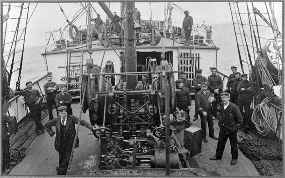
The picking-up and paying-out machine which we illustrate is extremely compact, though it is a double machine and is designed to pick up cables under a strain of 20 tons, it only weighs only 9¼ tons, and occupies a deck space of 8 ft. 3 in. by 11 ft. 6 in. It is very similar in design to the gear recently fitted by Messrs. Johnson & Phillips on the Japanese Government steamer, except that it is not quite so powerful and has horizontal engines instead of vertical. The machine is built on two frames made of steel plates, with steel angles inside and outside, with welded corners. The drum shaft, which has large collars welded on for attachment to the frame, ties them well at the top. The forward bottom ends are tied by a steel plate and also by a flange shaft, which carries the fleeting knives and takes the eyes of the main brake straps. There is also a “T” bar stay at the bottom after end, as well as diagonal stays at each end of the pairs frames, thus making a very stiff job and allowing of the whole of this part of the gear being lifted out in one piece without fear of the shafts or bearings getting out of line.

Picking-up and Paying-out Machine |
The machine is designed for two speeds, which can be geared on to either drum, but the port drum only is intended for the heavy lift of twenty tons, for which purpose it is built in steel, whereas the starboard drum is of cast iron. These drums are 6 ft. 7 in. diameter by 2 ft. wide over all. They are internally geared and have a rim cast on for main brake, and so combine main drum, brake drum, and gear wheel. These drums are arranged to run loose on the shaft and are capable of many combinations with the gearing as follows:—Both drums can work loose without the engine. Both drums can work at the same speed with the engine. One drum can he driven by engine while the other runs independently. One drum can be held by brake while the other is being worked by engine. Power of both brakes can be put on to one drum by keeping the pinions in gear.
All wheels are arranged to draw out of gear where possible when not required for driving, so as to avoid rattling. In the case of the pinion which gears with large drums this necessitated cutting large holes in the frames so that the pinion could pass right through them. The frames at these parts are provided with large circular cast iron pockets, which carry bearings at each end, so that when the pinion is in work it is close up to a bearing, thus ensuring a very sound job. The brakes consist of steel straps with elm blocks attached, the ends of the straps being fitted with steel castings, which carry nuts with right and left hand threads to take the brake screws. The screws and rods are taken down to the after end of the machine so as to be worked from the main deck. The lower part of the brake strap is fitted with a large cast iron eye, which transmits the strain to the lower part of the machine frames by means of a steel shaft, which is secured to the frames by large cast iron flanges.
Hauling-off gear is driven by a chain from intermediate shaft, so that its speed is always proportionate to that of the drums. For holding back purposes the sheaves have a brake rim cast on them, and on these rims a steel strap with screw adjustment is fitted, so that the amount of “drag” put on the cable can be adjusted minutely. The sheaves can slide along on their shaft to suit an inside or outside lead.
A small Worthington pump is fixed between the frames to supply the main and holding back gear brakes.
The engine has cylinders 9 in. and 16 in. by 10 in. stroke, suitable for steam 160 lbs. per square inch, and it is complete with automatic bye-pass valve, steam valve, and link motion reversing gear, all of which with the main and holding back brakes are within reach of one man at the after end of the machine. The gear was run under steam pressure at Messrs. Johnson & Phillips's works, and also on board the vessel to the satisfaction of the consulting engineers, W.H. Preece, Esq., and W.H. Culley, Esq., of H.M.T.S. Alert. The bow gear consists of two steel sheaves 3 ft. 2½ in.diameter by 11½ in. wide, which run loose on a steel shaft supported in cast iron brackets attached to three steel girders. Each sheave is provided with whisker guards to prevent the cable getting off the sheave, these guards also being bolted securely to the whiskers. The girders are fitted with eyes and bollards to secure the stoppers. A davit is provided between the sheaves for launching mushrooms, etc., and is arranged to fold down out of the way when necessary to let go the bight.
The vessel is fitted with the usual dynamometers, lead wheels, deck leads, troughing, &c., and is fully equipped with a complete outfit of stores and accessories, including grapnel and buoy ropes, grapnels, mushrooms, buoys, chains, sounding shot, steam sounding machine, steam hauling gear, &c., and the testing-room is provided with a set of first-class instruments.