Introduction: Allan Green's article describes and illustrates an unusual landline cable which was discovered recently near the Telegraph Museum at Porthcurno, Cornwall. For a short history of the Porthcurno cable station, and photographs of the area, see this page.
I'm sorry to report that Allan Green died in October 2022. He was a good friend and a very well-regarded researcher into cable history, always generous with his time and knowledge, and will be sadly missed.
|
Investigation of a cable sample found in a
field
near the Porthcurno Telegraph Museum
by Allan Green
Location of the find:
The cable was turned up by plough in a field above the Telegraph Museum, part of Trendrenan Farm and at approx OS map reference SW (to be added). A further sample was found in a nearby hedgerow. Both finds were made in early May 2007.
Object of the study:
To determine the basic cable design and construction, its possible use in the location and particularly to determine if it was possibly related to late 19th / early 20th century telegraph communications. The initial though was that it may be one of the early 20th century submarine telegraph land lines (Porthcurno to Penzance) but it is also possible that it was associated with a nearby site where early radio masts had been located.
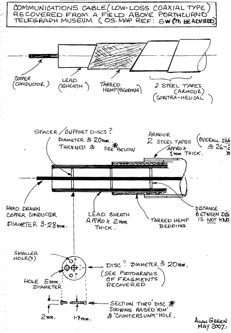
Examination carried out: The samples were photographed as received and then with great difficulty cut up / open to reveal inner construction and component parts. Photographs were taken of various components (See images 1 to 10). The component parts were measured and a sketch (Fig 1, at end of article) was made indicating the parts and dimensions. The sketch also indicates initial thoughts as to the possible type of construction of the cable
Conclusions:
To-date it is not possible to draw any definite conclusions about either the design construction of the cable or its use although it would seem more likely to have been a radio related rather than telegraph cable.
Since work on the recovered samples continues, this report should be regarded as provisional. It is expected that further samples may be recovered which may give us additional information.
Description of the cable samples as found:
The samples were approx 100cm and 70cm in length. Most of the work was done on the longer length. The shorter piece was too badly damaged to be of use.
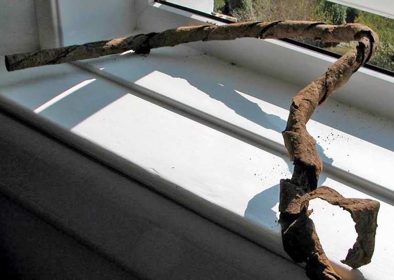
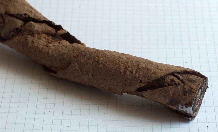
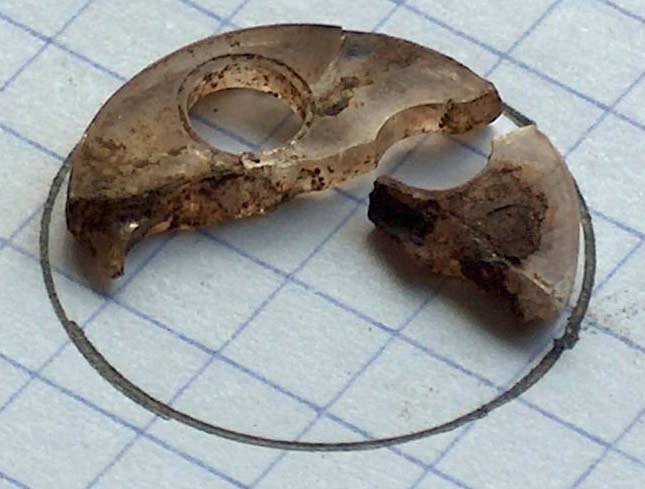
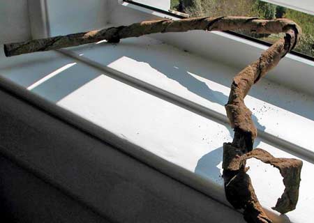
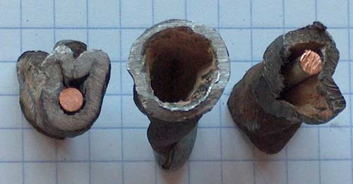
Images 1 and 2 show the longer sample.
1 |

2 |
There was heavy corrosion of the steel outer tapes which were bent and buckled probably due to being snagged by the farmer’s plough. It was evident, presumably as a result of the same snagging by the plough, that the sample had also been severely stretched.
General construction of the cable:
The pictures and the drawing show that the cable comprises 5 component parts. From the centre outwards
-
A copper conductor
-
An air space
-
A lead tubular sheath
-
A layer of tarred fibres
-
Two steel armour tapes

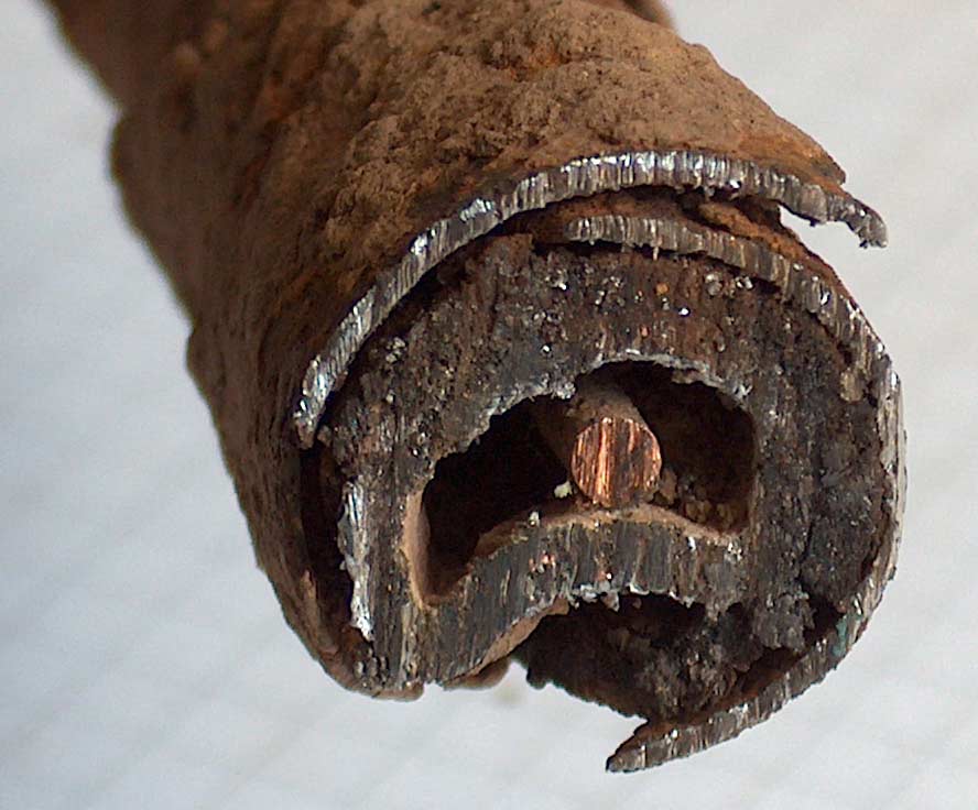
3 |
Description of each component:
The conductor is hard-drawn copper. The diameter is 3.28mm (0.130”) which is 10 gauge. Being hard drawn it would have 2 to 3 times the tensile strength of standard annealed copper. The surface was slightly corroded with traces of a whitish deposit.
The space between the conductor and the lead sheath appears to be mainly air, however, due to the cable being so badly twisted and stretched this space varied between zero and 15mm or more (see Image 10).
10 |
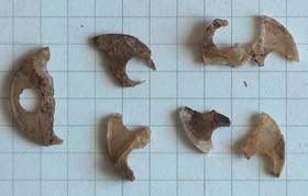
Various sections of cable were cut and at each point a number of material fragments either fell out of the space, or were found to be trapped in it. As well as sand and a few insects a number of small fragments of rather dirty transparent material were found.
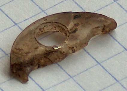
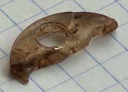
Image 4 shows a collection of these fragments. The largest single piece is shown in image 5 and measures 18mm x 8mm x approx 1mm thick.
4 |
5 |
-
At first sight the material appeared to be mineral, perhaps mica. It was brittle and even those few pieces which were intact carried cracks.
-
Simple tests were carried out in order to try to establish the true nature of the material.
-
Cleaning in water revealed a shiny smooth surface on most of the fragments.
-
Abrasion using sandpaper created a scratching and whitening of the surface
-
Immersion in acetone softened the sample.
-
Sample ignited and burned with black smoke when exposed to gas flame.
-
Sample appeared to be unaffected by boiling water.
-
Heating above 100C caused the sample to melt (no means available to measure actual temperature but probably > 200C.
8 |
The lead sheath indicates that the cable was almost certainly designed for service underground and probably for direct burial.
Although badly distorted by being snagged and stretched by action of the farmer’s plough we can see that the overall internal diameter was approx 20mm and that the wall thickness was around 2mm.
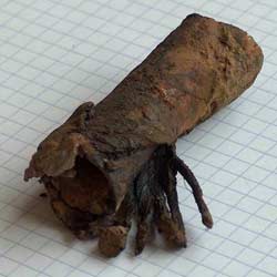
The layer of tarred fibres over the lead sheath are typical of the type of bedding used on armoured cables from earliest times. The fibres are probably hemp and comprise a number of small bundles which are laid helically around the lead sheath (see image 8) and are impregnated with tar or similar compound. The main purpose of the bedding in this cable would seem to have been simple mechanical buffering between lead sheath and the tape armour to prevent abrasion and possible electrolytic action (?)
The two steel armour tapes are laid contra helically over the fibre bedding (see image 2, above).
The tapes are quite heavily corroded and were probably made of bright mild steel without protection. They are approx 1mm thick and abut 40 to 50mm wide.
In the UK steel tape armour such as we see here is not very often used. Most manufacturers and BS specifications go for steel wire armour (SWA) or steel wire braid (SWB).
Continental manufacturers, particularly the French use steel tape much more frequently. The original thought was that this MUST be a French cable but it now seems quite possible that it could have come from a UK or even US manufacturer.
Some further thoughts:
It seems likely that the plastic fragments recovered from the ‘air space’ were originally dielectric spacer discs or components used to separate the inner conductor from the lead outer. In the mid 20th century as higher frequencies were adopted for radio transmissions various means were sought to design low loss cables with dielectric constant as close as possible to unity (vacuum) e.g. for use as antenna feeders particularly where antennae might be sighted a long distance from the transmitter.
In the 1950’s and 60’s companies such as Phelps-Dodge in USA developed cables like “Styroflex” which used a helical membrane separator and it is sure that other manufacturers used discs of various types, and materials to try and achieve the same, low loss characteristics.
Various plastic materials were used including polystyrene, acrylics and also PTFE.
These designs were the forerunners of the helical membrane low loss, high frequency cables manufactured today by companies like Andrews (USA) and RFS (Germany) and marketed under brand names such as Heliax.
Just how this particular cable was constructed internally remains a mystery for the moment.
In particular why did the discs have several holes in them?
Why was there no axial hole? Or was there one?
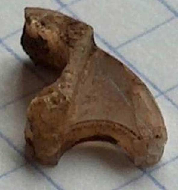
What is the “step’’ in the thickness of the fragment shown in image 7?
Why are the rims of each hole chamfered (countersunk)? See images 5 & 6
Allan Green
June 2007
Since posting the request we have found out just a little more about such cables.
Almost certainly it was a high frequency, high power, underground feeder cable for a radio transmitter and probably dating from around 1950 and manufactured for the Ministry of Defence or The Post Office. There were various war-time (and later) military communications installations in the area.
I have also found specifications in Post Office archives of very similar looking cables which used individual spacer discs like the one we found. It would seem that each disc was rather a horse-shoe shape with a narrow, open ended slot ( approx same size as the inner conductor) running from the rim to the centre and this allowed the discs to be fitted over the conductor and cemented in place at regular intervals.
The holes around the periphery of each disc which are visible in my pictures were to improve the dielectric constant of what was already a very low-loss cable. They were in effect no more than an air-space.
One of the speccifications I have seen shows Siemens as the manufacturer although we cannot say that our particular cable was made by them.
This type of construction was clearly very expensive and it would seem that it was around for only a short time. New designs soon followed from Andrews (USA) and Kabelmetal ( later RFS Radio Frequency Systems inside Alcatel Cable Group) using a continuous helical membrane to achieve similar characteristics and are in use today. |