History of the Atlantic Cable & Undersea Communications
from the first submarine cable of 1850 to the worldwide fiber optic network
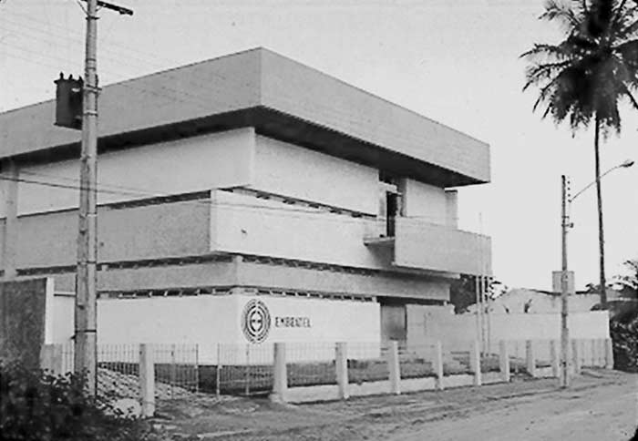
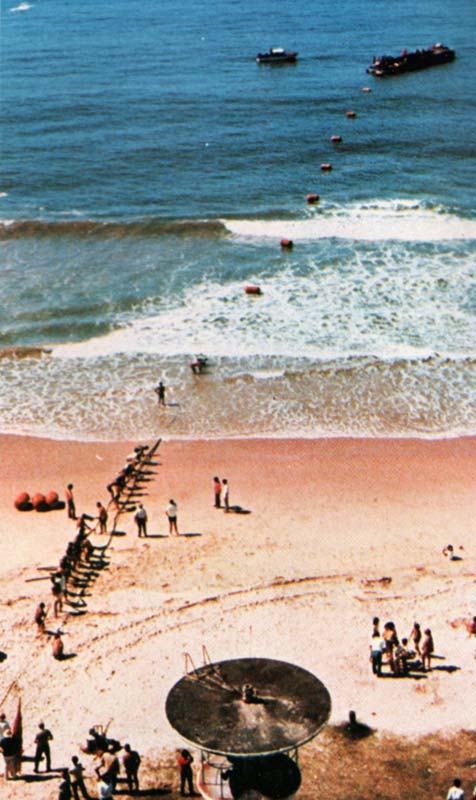
1973 BRACAN-1 (Brazil - Canary Islands) Cable
by Bill Glover
|
History of the Atlantic Cable & Undersea Communications |
|
1973 BRACAN-1 (Brazil - Canary Islands) Cable |
|
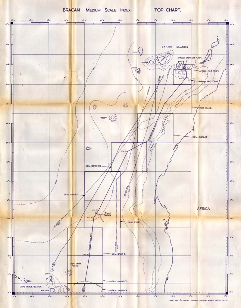
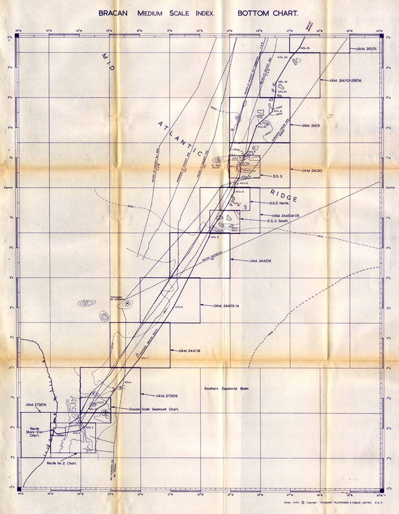
BRAZIL - CANARY ISLANDS RECIFE - GRAN CANARIA Report on the Deep Sea survey carried out between Recife, Brazil and Arinaga, Gran Canaria, by 1 ) The CS Retriever (5) during the period 11 th May 1971 to 11 th June 1971 and also by 2) The CS Recorder (3) during the period 13 th June 1971 to 20 th July 1971. Prepared by: Standard Telephones and Cables Ltd., 190 The Strand, London, WC 2. 1.0 INTRODUCTION A deep sea survey for the BRACAN - 1 submarine telephone cable system was carried out by STC between Recife, Brazil and Arinaga, Gran Canaria, using the CS Retriever (5) and the CS Recorder(3) both vessels being owned by Cable and Wireless Ltd. The survey commenced at Recife on Tuesday, 11 th May. Following the transfer of the survey party from the CS Retriever (5) to the CS Recorder (3) at Las Palmas on Saturday, 12 th June, the return to Recife was completed by Sunday, 27 th June and the survey finally completed at Las Palmas on Tuesday, 20 th July. A satisfactory route was selected between the landing sites making allowance for adverse topography, particularly in the area of the Mid-Atlantic Ridge, for existing telephone and telegraph cables and for potentially hazardous areas as revealed by the cable fault histories. The distance between the joint at Recife and the beach joint at Arinaga Bay, along the selected route, is 2542.90 nautical miles. PERSONNEL
2.0 INDEX
3.0 DIARY OF EVENTS
Sunday 9th May 1971 The CS Retriever (5) arrived off Recife at 17.00 and anchored overnight. Monday 10th May 1971 The CS Retriever (5) berthed alongside at Recife and was joined by the survey team comprising Sr. L.F.E. Bezerra, Sr. A. Zafra Gonzalez, Mr. J.H. Neal, Mr. J. J. W. Everett, Mr. J. E. Holmes, Mr. A. P. Craggs, Mr. I. F. Bennett and Mr. D. R. Martin. Tuesday 11th May 1971 The CS Retriever (5) left the berth at 07.40 but did not leave harbour until 12.20. The survey commenced at 13.30 with sample survey runs over the continental shelf and continental slope. Wednesday 12th May 1971 Temperature and core stations carried out all day. Thursday 13th May 1971 Temperature and core stations continued. Marker buoy for the first development survey (DS1) laid and first camera station carried out. Friday 14th May 1971 Further temperature stations carried out. Development survey commenced, using marker buoy as prime navigation reference. Saturday 15th May 1971 and Sunday 16th May 1971 Development survey continued. Monday 17th May 1971 Development survey grid completed, a final camera drop carried out and marker buoy recovered. Main survey continued. Tuesday 18th May 1971 Main survey continued. Survey grid carried out over two sea mounts to check area between, Wednesday 19th May 1971 Survey grid completed. Thursday 20th May 1971 Main survey continued, with existence of two possible sea mounts adjacent to route checked. One existed, one could not be found. Friday 21 st May 1971 Main survey continued to southern edge of Mid-Atlantic Ridge. Core and temperature station taken just south of ridge. Commenced exploratory sounding runs of southern ranges of ridge. Saturday 22nd May 1971 Exploratory runs continued. Sunday 23rd May 1971 Exploratory runs completed and most promising area selected for detailed development survey (DS2). Monday 24th May 1971 Marker buoy laid and development survey commenced. Core, temperature and camera stations carried out. Tuesday 25th May 1971 Development survey completed. Core and temperature station carried out. Exploratory sounding runs of northern ranges of ridge begun. Wednesday 26th May 1971, Thursday 27th May 1971 and Friday 28th May 1971 Exploratory runs continued. Saturday 29th May 1971 Exploratory runs completed and marker buoy laid for detailed development survey (DS3) Sunday 30th May 1971 Development survey completed and a camera drop carried out. Monday 31 st May 1971 Survey run southwards. Tuesday 1 st June 1971 Marker buoy for DS2 recovered. Survey run continued northwards. Wednesday 2nd June 1971 Two core and camera stations carried out. Marker buoy for DS3 recovered. Survey run continued northwards. Thursday 3rd June 1971 Sounding grid runs over features to north of ridge carried out. Friday 4th June 1971 Grid work stopped and sounding run commenced northwards. Saturday 5th June 1971 Sounding run finished and headed directly for St. Vincent, Cape Verde Islands. Sunday 6th June 1971 In transit to St. Vincent. Monday 7th June 1971 Arrived St. Vincent. Mr. E.J. Fellows embarked. Tuesday 8th June 1971 Left for Las Palmas to transfer survey to CS Recorder (3). Wednesday 9th June 1971 Thursday 10th June 1971 In transit to Las Palmas. Friday 11th June 1971 Arrived Las Palmas. Berthed alongside CS Recorder (3).
Saturday 12th June 1971 Transfer of survey personnel, equipment, records and SatNav completed. Mr. M.J. Hall joined survey team. Mr. J. J. W Everett and Mr. I. F. Bennett departed for UK. Sunday 13th June 1971 Departed Las Palmas. Survey re-commenced with temperature and core stations off Arinaga Bay landing. Monday 14th June 1971 Exploratory sounding runs down continental slope. Tuesday 15th June 1971 Exploratory work completed. Further temperature and core stations. Single sounding run into Las Cruces bay. ITT SatNav engineer disembarked off Las Palmas. Further temperature and core stations. Main survey run southwards commenced. Wednesday 16th June 1971 Survey run southward. Thursday 17th June 1971 Survey run southward. Investigated rift valley feature. Friday 18th June 1971 Survey run northwards to connect with previous sounding work. Saturday 19th June 1971 Survey run re-commenced southwards Sunday 20th June 1971 Investigated small feature. Continued survey run southwards. Computer unit of SatNav apparently damaged beyond repair, by unknown cause. Monday 21 st June 1971 SatNav confirmed to be unserviceable. Survey crossing area of SAT-1 cable. Headed along route for Recife, using astro-navigation. No detailed survey grids to be carried out due to lack of high accuracy position fixes. Tuesday 22nd June 1971, Wednesday 23rd June 1971, Thursday 24th June 1971, Friday 25th June 1971 and Saturday 26th June 1971. Survey run continued southwards. Numerous features, both anticipated and unexpected, found but not investigated. Astro-navigation conditions often proved difficult. Sunday 27th June 1971 Arrived Recife. Berthed alongside. Monday 28th June 1971 Dr. H. Richard visited ship. ITT SatNav technician arrived and endorsed diagnosis of faulty computer. Customs problems causing delay in arrival of spare parts. Mr. M. J. Hall and Mr. D. R. Martin disembarked and returned to UK. Tuesday 29th June 1971 and Wednesday 30th June 1971 SatNav spare parts still delayed. Thursday 1 st July 1971 Spare parts arrived aboard CS Recorder (3) and SatNav repairs carried out. Friday 2nd July 1971 SatNav functioning correctly. Departed Recife. Survey re-commenced with confirmatory sounding run off Boa Viagem landing site. Saturday 3rd July 1971 Confirmatory sounding run continued northwards. Small box carried out over sea mount adjacent to route. Continued northwards. Sunday 4th July 1971 Continued sounding run northwards. Monday 5th July 1971 Continued sounding northwards. Carried out one temperature station. Slow speed sounding run over area of complex topography in the Mid-Atlantic Ridge. Tuesday 6th July 1971 Slow speed sounding run continued. Carried out one temperature station, Continued confirmatory sounding run at normal speed. Wednesday 7th July 1971 Confirmatory survey over Mid-Atlantic Ridge completed. Survey of Sierra Leone Rise commenced. Several box sounding grids envisaged. Thursday 8th July 1971 Continued Survey. Friday 9th July 1971 Core station carried out. Continued survey. Sounding grids all carried out using SatNav navigation. No buoying or development surveys anticipated due to straightforward nature of features found. Saturday 10th July 1971, Sunday 11th July 1971, Monday 12th July 1971, Tuesday 13th July 1971 and Wednesday 14th July 1971 Continued survey of Sierra Leone Rise and of Cape Verde Basin. Numerous features investigated. Thursday 15th July 1971 Temperature station carried out. Continued survey run northwards. Friday 16th July 1971 Continued survey up to crossing with SAT-1 cable. Small sounding box carried out. Confirmatory sounding run continued northwards over Cape Verde plateau. Saturday 17th July 1971, Sunday 18th July 1971, Monday 19th July 1971 Continued confirmatory sounding run off African coast up to Arinaga approaches. Tuesday 20th July 1971 Sounding run completed. Two further temperature stations carried out off Arinaga Bay. Entered Las Palmas and berthed alongside. All survey personnel disembarked. 4.0 SURVEY METHODS Before the survey commenced a pre-survey study was carried out to bring together all the relevant information available that will assist the route selection. This data comprises soundings, cable positions and fault histories, temperature data and seismic data. A shore end survey consisting of an appraisal of the probable land cable route, the beach landing area, and the shallow water approaches to the shore has been carried out at both ends of the system. At Recife the initial work was carried out between 2nd and 7th December, 1970, with additional work between 1 st and 5 th May 1971. At Gran Canaria the survey work was carried out between 11th and 16th March 1971; The deep sea survey was then carried out to determine a satisfactory economical route between the landing sites. Pre Survey Study Before the survey commenced 1 :250,000 scale Permatrace charts were prepared showing relevant cable positions, cable fault details, sounding data and sea bed contours. The information was kindly provided by the following authorities. i ) Cable Cable and Wireless Limited London, UK. ii) Bathymetric Directoria De Hidrografia E Navegacao, Rio, Brazil Service Hydrographique de la Marine, Paris, France, MOD Hydrographic Department, Taunton, UK. iii) Temperature National Oceanographic Data Centre, Washington, USA. iv) Seismic National Oceanic Administration, Rockville, USA. The charts and data provided the basis for the survey campaign. Shore end Survey A shore end survey consisting of an appraisal of suitable landing areas and the shallow water approaches to the shore, together with the possible land cable routes was carried out prior to the deep-sea survey. At Arinaga Bay small boat work primarily using a portable echo sounder was carried out to supplement the existing chart information. Both small boat work and the use of divers were necessary at Recife to accurately assess the problems presented to the cable landing operation and the factors affecting the life of the cable. A separate report covering this work has been prepared and distributed and the landing sites at Boa Viagem and Arinaga Bay provisionally accepted subject to the findings of the deep-sea survey. Deep Sea Survey The aim of the deep sea survey was to gather additional information about the topography and nature of the sea floor, to assess the hazards of the environment to the cable, and to provide information necessary for the manufacture of the cable and for the laying of the system. These aims were accomplished as follows: Sounding runs were carried out over the whole route with detailed grid pattern runs over potentially hazardous areas. These areas were indicated either by the pre-survey charts or by extrapolation from the survey data. At each landing, sea bed temperatures were taken to enlarge and confirm the pre-survey data. Temperatures were also taken at selected points along the route to confirm the deep water temperature data already analysed. At specific points corer samples were taken in order to determine the nature of the sea floor, with use of the underwater camera being made whenever clarification was necessary. During the survey factors which would affect the route selection, e.g. existing cables and repeaters, cable fault areas, position and nature of the landing site approaches, were continually assessed. Factors affecting the laying of the system such as weather conditions, currents, and navigational accuracy were also assessed. 5.0 ROUTE SELECTION The provisional selection of the route was carried out on each section of the route following its initial survey. Final route selection was carried out during the final Recife to Las Palmas sounding run. Selection was carried out on the basis of providing a short economical route that will not hazard the system throughout its working life. A more detailed summary of the considerations involved in the route selection are given at the end of this report. Briefly, they include navigational accuracy during the survey and during the laying operations, the behaviour of the cable during the lay, recovery and repair of the cable and natural hazards to the system such as seismic activity, turbidity currents and cable suspensions, as well as fishing vessels and ships' anchors. The proposed route passes through the following regions in each of which the following special factors need consideration: 1 Recife Landing i) presence of the coral reef and bank inshore ii) position of numerous telegraph cables, many still operational iii) proximity of the harbour and consequent anchorage dangers. (These points have already been covered by the shore end survey report ) 2 Brazilian Continental Shelf and Slope i) nature of a significant slope 22 miles off Recife ii) nature of the continental slope in terms of gradient and relief iii) position of numerous telegraph cables, many still operational 3 Southern Equatorial Basin i) position of the route in relation to several sea mounts in the abyssal plain 4 Mid-Atlantic Ridge i) selection of the route through the complex features of the ridge with their sometimes severe gradients and large extent, particularly on the northern edge of the ridge ii) position of the Recife - St. Vincent No.2 telegraph cable. 5. Sierra Leone Rise i) selection of the route through a complex region of sea mounts, sea hills, ridges and rift valleys, generally decreasing in severity towards the north. 6 Cape Verde Basin i) position of the route in the region of many small features continuing northwards to 09° 15' W ii) position of the route between two sea mounts in latitude 09° 50' N. and close to a further mount in latitude 11° 02' N. iii) crossing of the St. Vincent - Ascension No.1 and No. 2 telegraph cables in latitude 11° 10' N. and 10° 30' N respectively. 7. Cape Verde Plateau i) crossing of the SAT 1 coaxial telephone cable and its repeaters at 14° 50' N. ii) positioning of the route to avoid a sea mount in latitude 14° 55' N in close proximity to the SAT 1 cable crossing. iii) positioning of the route to avoid an uneven area in latitude 18° 00' N 8. African Continental Margin i) positioning of the route to avoid uneven areas at the base of African continental slope ii) crossing of the St. Louis - Tenerife and Dakar - Casablanca telegraph cables at 24° 03' N and 23° 40' N respectively iii) positioning of the route in relation to the SAT 1 cable. iv) positioning of the route for the optimum crossing of a valley feature in latitude 20° 10' N. 9. Gran Canaria Approaches i) nature of the continental slope in terms of gradient and relief. ii) positioning of the route to avoid a steep sided gully in the continental slope iii) nature of the anchoring and trawling hazards iv) constriction of the landing by rock areas close to the mouth of the bay.
5.1 Recife Landing Alter-course 1 is positioned to give the route an adequate separation from the complex of telegraph cables to the north of the proposed landing point. It initially follows a line perpendicular to the beach, and parallels the Recife - Rio telegraph cable at a distance of 2.4 miles until alter-course 1. Owing to the presence of the flat rock area immediately offshore from the landing point the use of cast iron piping has been recommended in the shore end survey report. Over the outer bank, at approximately 1 mile offshore, EB armouring is considered adequate in view of the precaution of embedding the cable into the coral recommended in the shore end survey report. The remainder of the sea bed consists of sand and mud with small coral particles. It is considered that EB armouring will be adequate over this material down to a depth of 10 fathoms. Inspection of the cable by divers at least annually is recommended as a preventative maintenance measure. In view of the number and the power of radio-frequency transmitting stations in close proximity to the cable, screening of the cable over the outer coral bank where the water depth reduces to 3-4 fathoms in places is considered advisable. The use of screened cable over this bank until deeper water is reached at 1.5 miles from the beach is therefore recommended. The spare screened cable recommendation has been increased to allow this length to be replaced out to sufficient depth of water for a cable ship to carry out the testing and splicing of the cable and to avoid the need for a coaxial joint in screened submarine cable. As the closest safe point of approach to the beach for the laying ship is about 1 miles off-shore in a depth of 9 fathoms the use of a shallow draught vessel such as a small tug together with a lighter for the laying of the shore end cable to a distance of 2 miles from the shore is considered necessary. The proposed sea earth position is within the outer bank close to run 6 made during the initial Recife Shore End Survey. The earth plate position is at adequate distance from the transmission cable and in a depth of about 4½ fathoms adjacent to the inshore edge of the bank. The cable armour type is as for the transmission cable. As repair using a cable ship will be impossible in this area the spare cable recommendation consists of a complete replacement length of earth cable. 5.2 Brazilian Continental Shelf and Slope From alter course 1 the route runs directly towards the edge of the continental shelf. Seven telegraph cables are crossed in the section (4 working cables, 3 abandoned cables). This area was extensively surveyed during Development Survey 1 and it is considered that the route selected offers the most reasonable descent down the continental slope without encountering a more broken sea bed or steeper gradients. The slope is very broken in nature to the north of the selected route and for this reason is not acceptable. Further to the south the slope is less broken but is much steeper towards the top of the slope, typically 1 in 2. The route selected offers a smooth descent and a maximum gradient of 1 in 3 at the base of the slope. From alter-course 2 at the top of the slope inshore to alter-course 1 the route crosses a 250 fathoms slope at about 22 miles from the landing point. The sea bed samples and a camera drop here showed the presence of coral particles and broken shell material at the top of the slope, with only fine particles on the lower slopes. It is recommended that the E type armoured cable can be used down to 150 fathoms in order to give greater protection over the upper edge of the slope. The change over to lightweight cable occurs at 400 fathoms close to the gently shelving base of the slope. 5.3 Southern Equatorial Basin From alter-course 3 to alter-course 10 the recommended route runs across the relatively featureless abyssal plain from the foot of the Brazilian Continental Slope to the base of the Mid-Atlantic Ridge. Alter-courses 4 and 5 take the route between two large sea mounts at a nearest approach of 3 miles. Immediately to the north of these two features is a third, smaller sea mount which is passed on its eastern face also at a least distance of 3 miles. Alter-course 6, although very shallow in angle, takes the route to a distance of 2½ miles to the west of the steeper faces of a sea mount in latitude 06° 40' S. Alter-course 7 similarly takes the route 3 miles to the east of a small steep-sided sea hill in latitude 05° 40' S. The route then follows the initial survey track to alter-course 8, from where it bears northwards to join the route selected through the Mid-Atlantic Ridge. This section of the route has been covered by two sounding runs, a third having been the initial run up to the ridge further east of the proposed route. Closer to the Mid-Atlantic Ridge the proposed route converges on the Recife - St. Vincent No. 2 telegraph cable and maintains a minimum distance from it of 6 miles up to alter-course 9. In order to cross the southern slopes of the Ridge along an acceptable route this distance reduces to 4 miles at alter-course 10, the separation thereafter increasing steadily to 8 miles at alter-course 11. The only cable crossing in this region is that of the Recife - Monrovia telegraph cable in latitude 02° 35' S at an angle of 37 o. Sea bed samples taken in the basin both at the base of the Brazilian Continental Slope and of the Mid-Atlantic Ridge were of typical abyssal ooze and clay with no other particle material being present. 5.4 Mid-Atlantic Ridge From alter-course 10 to alter-course 20 is the most complex section surveyed. It consists of a series of parallel ridges and valleys running perpendicular to the proposed route. Many of the features found would pose hazards to the system and were avoided during the selection of the route. Other less severe features which would have been avoided elsewhere in areas of smoother relief must by necessity be crossed. The selected route is considered to be the optimum for this area and provides an acceptable margin of safety. An extensive survey was carried out over the southern section of the Ridge because of the lack of data available on this area. Six preliminary runs were used to find the least hazardous area, this being the region further to the west of area sounded. A detailed development survey was carried out here to provide sufficient information for route selection. This surveying procedure was carried out also over the northern region of the Ridge on the selection basis provided by five runs close to the most direct route towards Gran Canaria. Further runs were then carried out both to the east and the west in order to find a more suitable route area. Again, this region was to the west of the surveyed area. In order to maintain a reasonable separation from the Recife - St. Vincent No. 2 telegraph cable in this area it was necessary to cross this cable twice. The crossing angles are 44° in latitude 00° 40' N, and 40° in latitude 01° 10' N. From alter-course 10 to alter-course 11 the proposed route passes over a smooth-sided 700 fathom sea mount on the edge of the ridge before descending into a valley and skirting the edge of a complex feature at a distance of 2½ miles. The route then rises up to a large undulating feature approximately 30 miles wide, before again descending into a valley. From alter-course 11 to alter-course 12 the route passes 2 miles to the west of a 400 fathom rise in latitude 00° 25' S and then 3 miles west of a steep sided complex sea mount group also 400 fathoms high. Alter-courses 12, 13 and 14 take the route through a 5 mile wide gap in a 250 fathom ridge in latitude 00° 10' N, The distance from the Recife - St. Vincent No 2 telegraph cable is of necessity reduced to 2½ miles in this gap at alter-course 13. The separation steadily increases to 5½ miles at alter-course 14 at which point the route is 6 miles east of the steeper slopes of a narrow 600 fathom ridge in latitude 00° 22' N. The Recife - Dakar telegraph cable is crossed in latitude 00° 12' N at an angle of 38 o. In order to cross the complex and hazardous ridges and mounts in the northern region of the Ridge, between latitudes 00° 45' N and 02° 00' N, a route to the west of the Recife - St. Vincent No. 2 telegraph cable was selected. Although this means an average separation of 2¼ miles from the telegraph cable over a distance of about 40 miles, all of the major hazards are passed at an acceptable distance. From alter-course 15 the separation from the telegraph cable reduces rapidly to 1¼ miles immediately before the crossing. The only feature crossed is a 100 fathom saddle in latitude 00° 30' N between a 300 fathom sea hill 3 miles to the west and the eastern limit of a ridge some 200 fathoms high at 2 miles to the east. Between the alter-courses 15 and 16, necessary to cross the telegraph cable, a gap in a broken ridge is crossed in latitude 00° 38' N. A smooth 200 fathom rise on the eastern part of the ridge is passed at a distance of 1 mile and the steep gradients of the western part are passed at a distance of 3 miles. Immediately after alter-course 16 the gentle lower slopes of a 1000 fathom sea mount to the west of the route are passed at a distance of 1 mile. In view of the 47 degree course change at alter-course 16 the cable will bottom further eastwards away from this feature in the region of an acceptable 500 fathom slope up from the valley in latitude 00° 43' N. In latitude 00° 54' N the route passes between two sea hills each of 250 fathoms in height, and having a separation of 2 miles. In order that this gap is followed during laying a buoy will be used as a navigation aid in this area. The ocean currents change rapidly in magnitude and direction as the region is crossed, and could cause the 1 mile clearance from the sea hills to be significantly reduced should a poor set of satellite navigator fixes occur at this time. From alter-course 17 to alter-course 18 a 6 mile wide ridge is crossed at a suitable angle while maintaining a 2¼ mile separation from the Recife - St. Vincent No. 2 telegraph cable and remaining 1 mile east of a small gully feature on the north face of the ridge in latitude 01° 03' N. Alter-courses 18 and 19 take the route back across the telegraph cable in the area of a valley in 1900 fathoms. Up to alter-course 20 the route passes westward of two major features, a 1,000 fathom high sea mount in latitude 01° 20, N is passed at a distance of 9 miles, and the western limit of a 300 fathom ridge in latitude 02° 05' N is passed at a distance of 2½ miles. The sea bed samples taken on the Ridge were all made on the slopes or peaks of sea mounts and ridges rather than on valley beds where sedimentation is likely to be greater. All the samples consisted of abyssal mud and ooze some with some sand particles or small grit particles possibly of volcanic origin. No sea bed material likely to be hazardous to lightweight cable was found. 5.5 Sierra Leone Rise The Sierra Leone Rise extends approximately from alter-course 20 in latitude 02° 03' N to about alter-course 30 in latitude 07° 15' N. The nature of the seabed in this region is very varied with sea hills, ridges and rift valley features all being encountered during the survey. Unlike the Mid-Atlantic Ridge where the ridges extend for some considerable distance many of the features in the Sierra Leone Rise are localised and are avoided just as far as is necessary to provide a suitable profile. From alter-course 20 to alter-course 21 the route passes 4½ miles west of an 1100 fathom sea mount in latitude 02° 07' N At latitude 02° 26' N there is a small 200 fathom rise before the gradual descent to the Cape Verde Basin continues. Between alter-course 21 and 22 the route passes a 300 fathom sea hill and a 100 fathom rise in latitude 02° 57' N with a clearance of 2 miles be given to the steeper slopes of the sea hill. In latitude 03° 05' N a 400 fathom sea hill to the east of the route is passed at a distance of 2½ miles. Clearance, of 2½ miles, is given also to a 200 fathom rise to the east in latitude 03° 28' N From alter-course 23 to alter-course 24 the route passes over a 200 fathom high flat topped ridge 20 miles wide. On the northern slopes of the ridge an area of steep but acceptable gradient (1 in 3) to the east of the route is passed at a distance of 2 miles. Between alter-courses 24 and 25 the route is governed by the 400 fathom ridge shaped sea hill 2 miles west of the route in latitude 04° 30' N. The route then passes over a 50 fathom rise in latitude 04° 35' N, before passing 2½ miles west of the eastern extremity of a 200 fathom rise in latitude 04° 51' N. From alter-course 26 to alter-course 27 the route trends west in order to clear by 3 miles the uneven ground at the western extremities of probably ridges in latitudes 05° 40' N and 06° 00' N. Alter-courses 28 and 29 then take the route eastwards of two rises, one of 200 fathoms 5 miles away from the route and another of 100 fathoms 2 miles away, occurring on the upper edge of a 200 fathom slope. Up to the edge of the Rise about latitude 07° 30' N only one other major feature is passed. This is a 350 fathom ridge, in latitude 07° 25' N, with acceptable gradients of 1 in 7 on both faces. This feature is crossed close to its peak. A sea bed sample taken in this region close to the crest of a 200 fathom slope consists of 4½ feet of typical abyssal clay with no hard particles present. 5.6 Cape Verde Basin Although this region consists predominantly of an abyssal plain it also has some sea hill features present mainly along its southern edge close to the Sierra Leone Rise. From latitude 07° 30' N to alter-course 31 the proposed route follows the centre of the three survey runs carried out since no hazardous features were found until 2 sea mounts in latitude 09° 50' N, The western sea mount some 600 fathoms high has a secondary peak 12 miles east in longitude 24° 08' W. This peak is 350 fathoms high but with an unacceptably steep southern face both here and on the ridge joining the peaks. The route passes east of this sea mount in the 50 fathom high saddle between this feature and a 300 fathom sea mount 2 miles east of the route. Owing to the broken terrain found to the east of alter-course 31 the route at this position cannot be moved further south. Since this causes a large course change of 47° at alter-course 32 the latter was kept eastwards to ensure that the laid position of the cable will not be up the steep southern face of the secondary western peak From alter-course 32 to alter-course 33 the eastern limit of a 200 fathom feature is skirted by 4 miles in latitude 10° 05' N. Alter-course 33 aligns the route over a 250 fathom saddle between two 400 fathom sea mounts in latitude 10° 25' N and provides a suitable crossing angle 59° for the St. Vincent - Ascension No 2 telegraph cable. The route then proceeds across the abyssal plain to join the southward Canaries - Recife sounding run at alter-course 34. A severe 400 fathom feature, possibly a sea mount, is passed at a distance of 5½ miles in latitude 11° N. The St. Vincent - Ascension No 1 telegraph cable is crossed in latitude 11° 12' N at an acceptable angle of 59 o. A temperature station carried out in this basin accurately confirmed the pre-survey data for this area. From alter-course 34 northwards no features on either of the two sounding runs made in this area were found within the limits of the Cape Verde Basin. 5.7 Cape Verde Plateau The Cape Verde Plateau extends approximately from 14° N to 20° N and covers from alter-course 35 to alter-course 38. Only two features affecting the route were found in this area and were the eastern extremity of a 300 fathom high sea mount or ridge at the SAT 1 cable crossing and an area of uneven terrain in latitude 18° W. In latitude 14° 54' N the steep eastern limit of a large feature some 4 miles to the north and west of the route is passed at alter-course 36. This clearance is the minimum acceptable to allow for the cable pulling across the corner during laying. Using the data mentioned in the attachment covering laying aspects the estimated angle is of the order of 65 o. This is an acceptable angle of cross for recovery purposes in view of the fact that this is a working telephone cable. The point of intersection is mid-way between repeaters 159 and 160 of the SAT 1 cable. To achieve a cross mid-way between the appropriate two BRACAN 1 repeaters the slack can be locally varied to obtain an acceptable cable crossing. From alter-course 36 northwards to alter-course 37 in latitude 18° N the sea bed is featureless and gently shallows from 2200 fathoms to 1600 fathoms. At alter-course 37 the route passes over an irregular 50 fathom bank which rises slowly towards the west, suggesting that the eastern extremity of some feature was found. The change in course here is only 2 degrees, but is sufficient to provide an acceptable clearance of 4 miles for the unsurveyed western region of the bank. Up to alter-course 38 the sea bed gently deepens again to 2000 fathoms before passing over a rift valley feature in 20° N. No further features were found in this region of the proposed route. 5.8 African Continental Margin From about 20° N up to the approaches to Gran Canaria the route passes close to the base of the African Continental Slope with its uneven seabed and consequent hazards. Due to the need to cross a feature in 20° N at a point some 30 miles west of the initial survey track, the present route provides an acceptable safety margin from possible turbidity effects on the Continental Slope. The rift valley feature found at 20° N consists of a steep sided valley of the order of a mile wide and up to 100 fathoms deep. In the eastern and central areas the sides are near vertical and present considerable danger from cable suspensions. In view of the proximity of the continental slope the possibility of an acceptable crossing being found further eastwards was ruled out. The valley feature was found to widen and become broken up, rather similar to a river valley and delta, some 30 miles west of the initial survey crossing point. At the acceptable crossing point chosen there is an area about 3 miles wide consisting only of broken ground. The nature of the feature precludes safe laying of the system to the east of this area and is not acceptable because of the danger of suspending the cable. Alter-course 38 and 39 take the route across the centre of the broken-up region and thereby allow a suitable safety margin during laying. The crossing is at right angles to the feature at this point. Up to alter-course 40 no further features were found, There is an acceptable clearance at a close approach point to the Dakar - Casablanca telegraph cable in latitude 22° 05' N of 7½ miles. Alter-course 40 and 41 take the route across the Dakar - Casablanca and St. Louis - Tenerife telegraph cables at angles of 43° and 40° respectively in latitudes 23° 41' N and 24° 03' N. The distances of the alter-courses from the cable crossing positions minimise the reduction in the angles of crossing due to the cable pulling inside the alter-courses during laying. No features were found during the survey in this area, although the pre-survey study showed the presence of several valley features notably in latitudes 24° 32, N, 25° 10' N, 26° 08' N and 26° 20' N. Alter-course 42 was positioned to take the route clear of any possible hazard to the system from the latter two features in view of the incomplete knowledge available on sea bed movement hazards in the area off this slope. From alter-course 42 up to the base of the Gran Canaria Continental Slope at about 27° N no further features were found.
5.9 Gran Canaria Approaches From about 27° N to the landing point the route passes the eastern edge of a feature found in latitude 27° 16' N before passing up the slope to the off shore shelf area and then turning towards the landing area. The route taken over the continental slope was chosen as far west as acceptable. In latitude 27° 16' N the eastern limit of a sea hill or ridge was found. As the route cannot acceptably pass up the continental slope further west the route passes 2½ miles east of this feature. The presence in about 27° 25' N of a valley feature near the base of the continental slope and the uneven nature of the sea bed together with steeper gradients at the shallower part of the slope will preclude the selection of an acceptable route further west. The selected route passes 2 miles east of the valley feature and runs parallel to it and beyond it up to alter-course 44. 6.0 PLATES
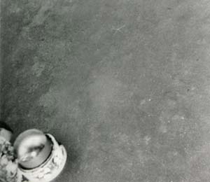
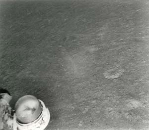
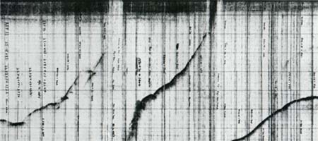
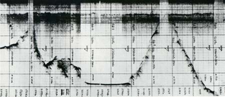
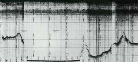
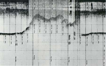
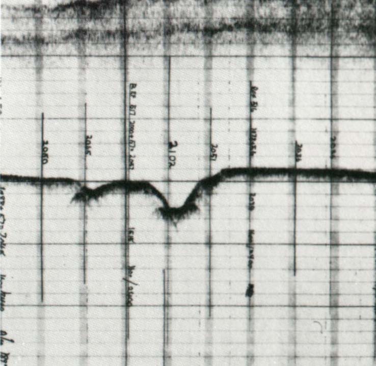
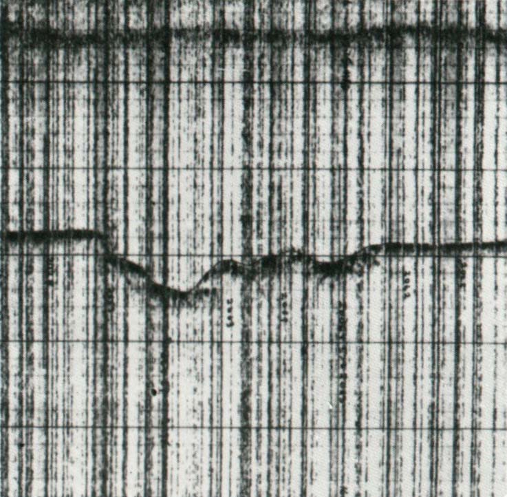
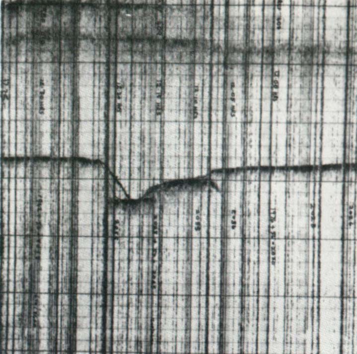
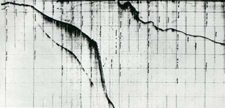
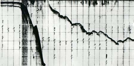
7.0 SURVEY EQUIPMENT The survey was carried out using ships operated by Cable and Wireless Limited, the CS Retriever (5), 4218 tons gross, based on Rio De Janeiro and the CS Recorder (3), 3284 tons gross, based on Vigo. The survey equipment used on both ships comprised the following: i) Kelvin & Hughes MS 38 Precision Depth Recorder with an accuracy of ± ½ fathom and a maximum range of 8,000 fathoms. Although the recorder is direct reading a small correction must be applied to account for the variation of the velocity of sound in water depending on salinity and temperature. Also, because of the constant pulse repetition frequency of the recorder the vertical exaggeration of the trace is dependent on the ship's speed and due allowance is made for this when calculating slope gradients. ii) Negretti and Zambra Reversing Thermometers for measurement of the sea bed temperatures. Although the reversing thermometer is a direct reading mercury-in-glass instrument it employs a second, correction thermometer. The main thermometer reading will alter due to the differential expansion between the low sea bed temperature and the high ambient reading temperature and must be appropriately corrected. iii) Cable and Wireless 150 lb Mark 2 Gravity Corer designed to provide crosssectional samples of sea bed material up to 6 feet in length in suitable bottom material. This simple gravity design operates well with all material except rock. iv) UMEL Underwater Camera based on an original Cable and Wireless design for seabed photography. The 35 mm still camera and flash units are activated by a bottom sensing trigger mechanism. A transducer unit provides pulses which register on the P. D. R. unit, thereby enabling the progress of the camera to be monitored. v) ITT 5001 Satellite Navigation Set operating from the US Navy series of navigation satellites. The set comprises units originally developed for US Military purposes. Frequency and accuracy of the position fixes are variable but are, on average, every 1½ hours and plus or minus ¼ nautical mile respectively. 8.0 ATTACHMENTS ATTACHMENT 8.1
ATTACHMENT 8.2
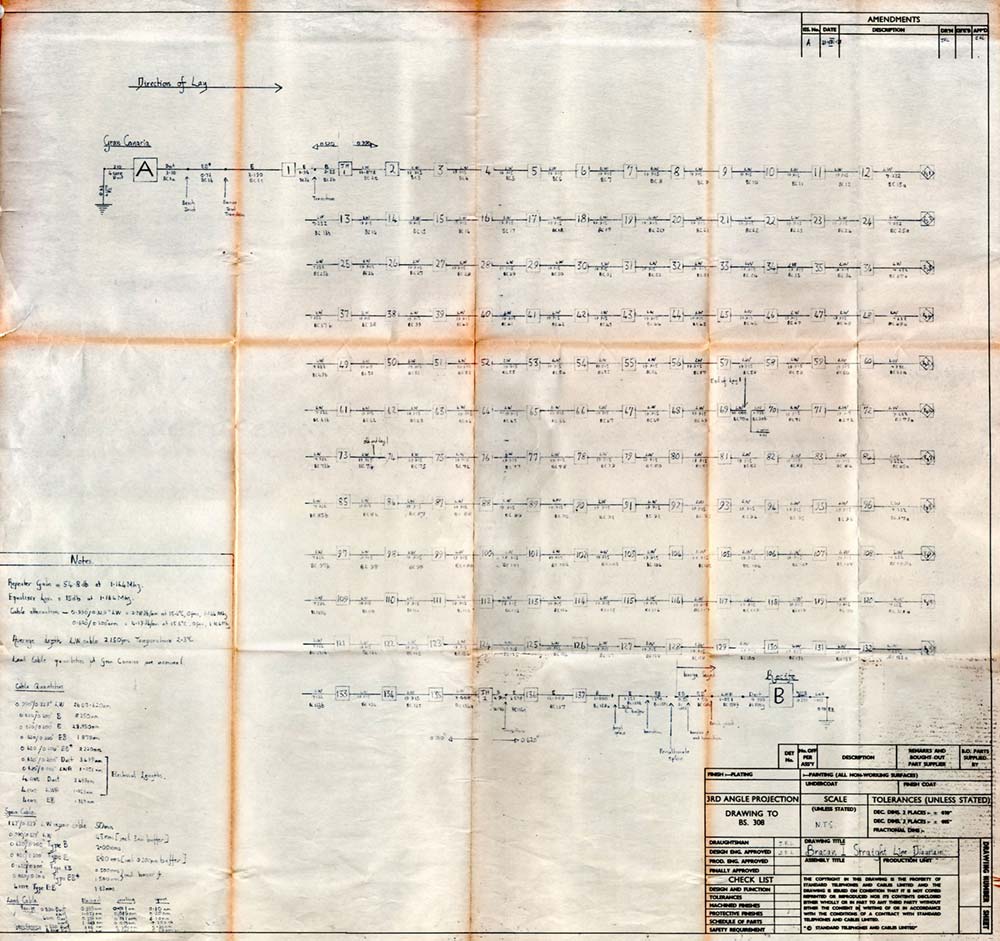
RECOMMENDED CABLE TYPES AND QUANTITIES
CABLE SUMMARY
NOTES: *1 An additional 25 metres has been included to allow for routing inside terminal station. *2 These lengths are provisional and will be revised on receipt of land route details. *3 0.20 nm of Duct cable as spare at Gran Canaria (provisional length dependent on land route details). 0.10 nm of Duct cable as spare at Recife. *4 This length includes the 0.20 nm laying buffer. *5 This length includes the 3.00 nm buffer between lays 1 and 2. The lightweight cable quantity is based on laying the minimum practical slack in the Southern Equatorial Basin, the Cape Verde Basin and Plateau and the African Continental Margin. Sufficient slack to enable the sea bed profile to be adequately followed during laying has been allowed over the Mid-Atlantic Ridge, the Sierra Leone Rise and the approaches to Recife and Arinaga. Higher slack values are also necessary over certain features, such as the rift valley at 20° N, occurring in the areas where low slack values are anticipated. The cut and hold method of repair will be necessary in the areas where minimum practical slack has been laid, The 7½ ton tensile strength of the cable, together with a cable weight in water of 0.60 ton/nm and a repeater weight of 0.5 tons gives a 230% safety margin during recovery under ideal conditions. This figure applies at the maximum depth of 2940 fathoms in the Southern Equatorial Basin with a repeater in suspension during recovery. Vertical movement of the cable ship will cause some tension variations, though less than those encountered if the bight recovery method were used under the same conditions with the same slack value. Over the Mid-Atlantic Ridge, the Sierra Leone Rise and the approaches to both landing sites the higher slack values present will enable the bight recovery repair method to be used. These areas are between 400 and 1500 fathoms shallower than the deepest point on the route. ATTACHMENT 8.3
ATTACHMENT 8.4 ROUTE SELECTION CONSIDERATIONS The following factors provide the basis for the selection of the route through the surveyed areas. Navigational accuracy during the survey For most of the survey the positional accuracy of the soundings is the accuracy of the satellite navigation system, This is about ± ¼ mile. Owing to the numerous intersections of the sounding runs the average positional accuracy will be better than this figure. Navigational accuracy during the laying operation Although this is dependent on the navigational method used it is also affected by the presence of ocean currents. In the period between position fixes it is possible for the ship to deviate from the route should the local currents be variable in magnitude and direction. Only at the time of a further position fix can the course be accurately corrected. An estimate of the currents throughout the selected route was made by Cable and Wireless and is included in the report. Behaviour of the cable during the laying operation Owing to the finite sinking speed of the cable (0.8 knots approximately for 0.990" BPO Mark 2 Lightweight cable) it is highly probable that the eventual sea bed position of the cable will not coincide with the ship's track. The amount by which they will differ will depend mainly on the magnitude and direction of the ocean currents, and on the magnitude of the course changes of the ship. The surface currents have been estimated throughout the length of the route and so can be allowed for during laying. Details of the sub surface and deep sea currents are not known, but their magnitude is expected to be comparable to the sinking speed of the cable. It was therefore advisable to keep the cable route away from hazards by at least the local depth of the water. The sea bed photographs over the Mid-Atlantic Ridge show the slight sea bed scouring that is consistent with the presence of deep water currents. The course changes have been kept to minimum angles consistent with keeping the route safely away from hazards. Because of the long descent time of the cable from the surface to sea bed (about 3 hours in a depth of 2500 fathoms) the cable will pull inside the corner of the alter-course by an amount dependent on the course change. In a depth of 2300 fathoms, with a laying speed of 6 knots and slack of 2% the distance will be up to 4½ miles at 60' course change. This figure is an estimate based on BPO cable data for 0.990" lightweight cable. Recovery and repair of the cable Should a repair become necessary in any depth of water the cable must either be hooked using a grapnel and hauled to the surface in a bight or cut on the sea bed and one cut end recovered with the cutting grapnel, with the other cut and being recovered separately. In either case it is necessary to drag the grapnel end its ground chain or rope across the sea bed until the cable has been hooked and hauled sufficient distance from its original position for the tension on the grapnel rope to rise. In order that this can occur satisfactorily it is necessary for the cable to be laid at sufficient distance from other cables to prevent the wrong cable from being caught and possibly damaged or cut. In deep water the grapnel rope will behave in a similar manner to the cable during laying in that it will bottom at a considerable distance from the ship and the position of the grapnel will be uncertain. The movement of the grapnel across the sea bed will also be imprecise. An adequate margin of safety must therefore be allowed when laying in the presence of other cables. Not only can interruption be caused to other working cables, but the repair to the cable in question could be delayed if recovery difficulties are experienced due to the close proximity of other cables whether working or abandoned. In view of the cost of lost revenue during a repair all cables have been crossed at an angle of not less than 35°. Natural and other hazards to the system The principal hazards liable to cause damage to the system are cable suspensions, seismic activity, turbidity currents, fishing vessels, and anchors. Cable suspensions, unless of significant magnitude, are not of themselves dangerous in deep water. They only present a hazard should movement of the cable be caused for some reason, thereby increasing the tension in the suspended cable beyond its tension limit. Earthquakes also, unless of significant magnitude, are not themselves dangerous. The main danger arises from the movement of dislodged material, particularly sediment that moves along with the associated turbidity current caused by the earthquake. This material, together with the current, can easily carry the cable and repeaters a considerable distance and can cause frequent system interruptions in areas of high seismic activity. The Mid-Atlantic Ridge does not have any particular areas of high activity hazardous to cables, although it is not earthquake-free, as is shown by the data in the attachments to this report. The SAT 1 cable has survived an earthquake whose epicentre was close to a repeater with no apparent effects. Fishing vessels, mainly trawlers and clam dredgers can cause cable damage if they hook the cable. The presence of trawlers off Gran Canaria together with the hard bottom material off the continental shelf has made it advisable to extend the B type armoured cable to 500 fathoms, just beyond the edge of the shelf, in order to minimise the possibility of trawling damage. Ship's anchors if they are dropped on to or are caught in the cable can easily cause breakages, as is shown by the pattern of the telegraph cable fault histories off Recife. For these reasons it is recommended that the landings in Brazil and Gran Canaria be made prohibited anchorage and fishing areas, particularly the Gran Canaria landing with its local trawling activity. ATTACHMENT 8.5 SEISMIC DATA SUMMARY
The period covered is 1961 to 1970 inclusive Data prior to this period was obtained before the international seismic recording network had been formed, Only shocks within 150 miles of the route and of magnitude 5 or greater have been given ATTACHMENT 8.6
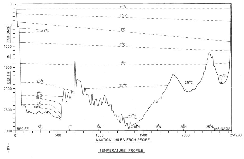
ATTACHMENT 8.7 TEMPERATURE PROFILE
ATTACHMENT 8.8
DRAWINGS
|
|||||||||||||||||||||||||||||||||||||||||||||||||||||||||||||||||||||||||||||||||||||||||||||||||||||||||||||||||||||||||||||||||||||||||||||||||||||||||||||||||||||||||||||||||||||||||||||||||||||||||||||||||||||||||||||||||||||||||||||||||||||||||||||||||||||||||||||||||
|
Last revised: 12 March, 2013 |
|
.jpg)
-BW.jpg)