Introduction: Edward O.W. Whitehouse, “Wildman Whitehouse” as he generally styled himself, was a surgeon by profession and an electrical experimenter by avocation. In 1856 he was appointed Electrician to the Atlantic Telegraph Company and was responsible for the testing of the 1857/58 cables, and for the design and operation of the equipment which would transmit the telegraph signals between Ireland and Newfoundland.
While there were other factors, the historical record generally reports that Whitehouse’s insistence on using high voltage induction coils was ultimately responsible for the failure of the cable. In this article, Stewart Ash analyses the cable failure from the point of view of current cable industry practice and experience, and presents a more nuanced explanation of the possible causes.
Stewart is an independent subsea telecommunications consultant with a career spanning over 45 years, and has written extensively on the history of the industry.Prior to starting his consultancy, Stewart spent 23 years with the leading system supplier, STC, and then 12 years with C&W Marine/Global Marine providing marine installation and maintenance services. Over his long career he gained a wealth of knowledge of cable design and manufacture and an in-depth understanding of jointing techniques. He has been involved in and led several investigations into insulation faults on working submarine cables.
|
Electrical Failure of the 1858 Atlantic Telegraph
Stewart Ash
It should be recognised that in the mid nineteenth century the science of electricity was in its infancy and such things as cable capacitance, dielectric strength and inductive surge were barely recognised phenomena, let alone understood. At the same time, the design and manufacture of complex structured submarine cables was also just starting.
The failure of the 1858 Atlantic Telegraph occurred because the insulation resistance was first impaired and then the insulation failed, creating short circuits. These took the electrical signals sent down the cable to sea earth at the short. As Donard de Cogan has indicated in his paper, the dielectric strength of pure gutta percha is on the order of 20-30kV/mm, and so only a very thin covering of pure gutta percha should be able to survive the repeated application of 2,000V, which Wildman Whitehouse’s equipment was apparently capable of delivering.
Before moving on there are two significant points to be made:
- As Donard has stated, the gutta percha used was unlikely to have been pure and would have contained a range of contaminates with varying electrical properties. Therefore, it is almost certain that the gutta percha used by the Gutta Percha Co would have had a reduced dielectric strength and that this would probably have varied quite considerably from batch to batch.
- We have no way of calculating the inductance of the cable and Whitehouse’s test set up, so it is impossible to know the peak surge voltage that could have been applied to the circuit when the source voltage was removed. This could have been well in excess of 2,000V.
Even with the above reservations, the cable as designed should have been able to survive Whitehouse’s test regimen. Therefore, the manufacture of the cable and its subsequent handling must have contributed to the condition of the cable through which Whitehouse tried to send messages.
Failure Mechanisms
Electrical insulation failures in cables occur for a number of reasons; these are as follows:
- Contamination of the insulant
- Degradation of the insulant
- Movement of the conductor within the insulant
- Rupture of the insulant from within
- Penetration of the insulant from outside
In modern day investigation sabotage has to be considered as a possible failure mechanism, but in this case this can probably be ignored.
If we follow the manufacturing process for the cable, possible problem areas can be identified which lead to one or more of the above causes of failure.
The Cable Design
The drawing below shows the cross section and structure of the deep water cable deployed:
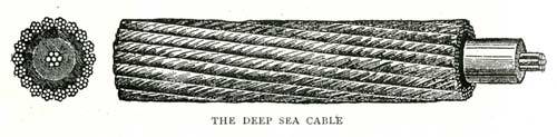
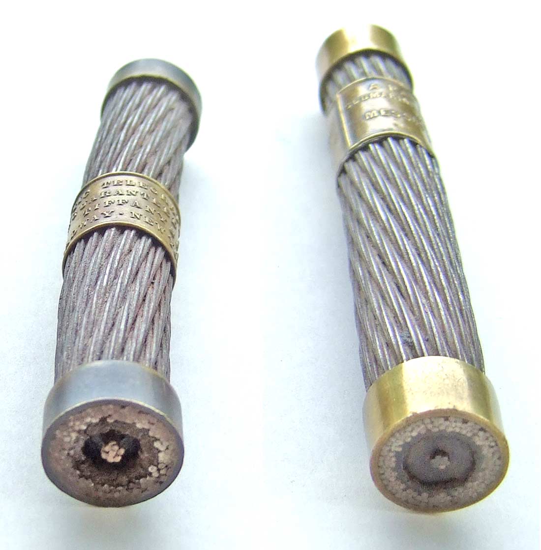
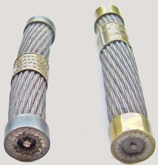
The cross section can also be seen in the cable pendant shown below which was made from the cable manufactured at Glass, Elliot & Company in Greenwich in 1857. It can be seen that the stranded copper conductor is offset slightly from the centre of the gutta percha insulant.
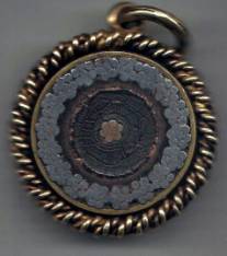
Cable Pendant
Manufacturing
It should be noted that the initial 2,500nm (nautical miles) of cable was manufactured in just six months in 1857. This is an extremely short period of time for such a volume of cable. Today, such a length of armoured cable would take between 12-14 months to manufacture.
The entire 2,500nm of cable core was manufactured by the Gutta Percha Co, in London. Half of the core was then transported to R S Newall & Co in Birkenhead in Liverpool and the other half to Glass, Elliot & Co in Greenwich.
Gutta Percha Company
As can be seen, the copper conductor is made up of a centre strand with six strands wrapped helically around it. The quality of this drawn copper was of its time. It could be brittle and have protrusions. Control of the laying up process could also allow one or more of the strands to stand proud. Brittle strands could result in breaks, which, like protrusions on the copper, if not spotted during manufacture could produce electrical stress points.
As already indicated, the quality of the gutta percha with regard to included contaminants would be a significant factor in the dielectric strength of the insulant, especially if any of the contaminants were metallic in nature. These metallic particles are known in the industry as ‘inclusions’ and adversely affect the dielectric strength by creating electrical stress points in the insulation. The significance of these inclusions depends upon their size and location within the insulant. Also, if the extrusion process does not remove all of the air, then air bubbles or voids can form in the insulant, often trapping moisture when the gutta percha cools. These again would undermine the dielectric strength of the insulant. Once extruded over, any broken strands or protrusions in the copper could rupture the insulant, and these would not be visible from the outside unless the rupture was so bad that the strand penetrated the insulant. Today, these problems rarely occur, but all can be detected by insulation tests and then located by X-ray techniques, neither of which were available to the Gutta Percha Co.
Gutta percha only becomes malleable above 60° C. We do not know what temperature the gutta percha was raised to in the extruding machine, the tension on the strand passing through the extruder, how it was cooled before coiling on to drums, or the diameter of these drums. The possibility therefore exists that the process of coiling the cable core onto a drum was carried out when the gutta percha was still hot, and the tension was such that the complete copper strand was moved to the inside of the turn on the drum. It is also possible that brittle copper strands could break during this process and once again only be observed if they penetrated the core. The turns on the inside diameter of the drum would have been most vulnerable to this, as they would experience the minimum bending radius. They would then be covered by subsequent turns so even severe ruptures may have gone undetected.
Storage & Transportation
We know that the core was transported on drums but not how it was protected during transportation or how it was stored at the two armouring factories before being brought to the armouring machines. As Donard has indicated, if the core was kept in a damp humid environment then degradation of the gutta percha due to bacterial fermentation is a possibility. Alternatively, if the core was not protected and was exposed to direct sunlight for any length of time, then degradation due to actinic radiation is another consideration.
Glass, Elliot & Company
We need only consider one of the two armouring companies. R S Newall used a right-hand armouring lay and Glass, Elliot used the now conventional left-hand lay for the armour wires. This difference in itself is unlikely to have had any impact on the insulation performance of the cable.
 |
Right-hand lay
Newall |
Left-hand lay
Glass, Elliot |
During the armouring process, hemp roving is applied to the core to form a bedding for the armour wires. The tension of the roving must be properly controlled, as otherwise it can indent the core and create a weak point in the insulation. Once the armour wires overlay the hemp, this type of issue cannot be visually inspected.
Once again, the quality of the armour wires was of its time. They could be brittle, break, and penetrate the core. If this occurred, then once the outer hemp rove was applied this again could not be inspected.
We know that throughout these manufacturing processes there were very few quality inspection points, no testing of the insulation performance of the cable, and the finished cable was stored in open field tanks. We do not have information on the minimum bending radius that the cable experienced or the height of the coils, which would indicate the crush forces that the lower flakes of the coil experienced. Nor do we know the temperature range and the number of temperature cycles that the cable experienced. Each could be a factor in deforming the cable structure and undermining the dielectric strength. This is discussed further in the next section.
Cable Loading
The cable was hauled onto HMS Agamemnon and the USS Niagara where it was coiled into large tanks. Again, coil height and minimum bending radius would be significant factors. Obviously the bending radius of each piece of cable would depend on its place in the coil, the cable in the centre being under more strain than the cable on the outside. We have no information about the minimum bending radius that the cable was subject to but this process could have resulted in in the breaking of brittle copper strand wires or brittle armour wires, rupturing or penetrating the insulant. It is also likely that the diameter of the ships tanks was less than the factory field tanks and therefore the heights of the cable coils would be greater. This would mean the lower turns would be subject to greatest crush forces, which could have distorted the cable structure. Also, during passage, the cable coil tends to settle, taking up the gaps left during the manual coiling process and thus increasing the compression forces on cable in the tank.
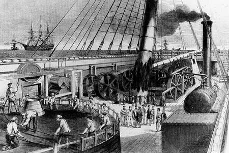
Paying out the Atlantic Telegraph Cable from the deck of the United States Steam Corvette Niagara
From the Illustrated Times of London, 15 August 1857 |
It should also be remembered that these were steam ships with steam piped all over the vessel, so it is possible that areas of the coil touching the tank walls could have been subject to local heating. This may have raised the cable temperature to such a level that the gutta percha became sufficiently malleable that gravity and or the ship’s motion could cause the strand to drop within the core.
Further illustrations of the machinery used in manufacturing the cable, its storage conditions after manufacture, the loading and handling on board ship, and the stresses and strains it encountered during laying, may be found on the 1857-1858 Atlantic cable page.
Storage at Plymouth
The cable was stored in sheds in Plymouth for a long period of time. Minimum bending radii and coil heights are again significant. The coils were open to the air so the possibility of degradation of the insulant due to bacterial fermentation must be considered. I do not believe the temperatures in the sheds could have been raised to such an extent that the gutta percha became malleable, but I suppose it is possible. Creep or cold flow of the gutta percha during storage is also another possible mechanism that could have compromised the cable insulation. This would have had greatest impact on the cable at the bottom of the coils, due to their being subject to the greatest crushing forces.
Cable Joints
The cable was, of course, not manufactured in one continuous length; numerous joints were made in the factory and in the field to complete the manufacture and insulation. Cable joints are a potential source of insulation impairment. In the factory, the short sections of core would have been joined together in order to manufacture longer lengths of cable. Then full cable-to-cable joints would be made between different armour types and to increase the section length of the same type of armour. In the field, all joints would have been cable-to-cable and were required to facilitate the loading and installation of the cable. We also know that while in storage in Plymouth, the cable was cut for testing purposes and new joints inserted.
To make a cable-to-cable joint, the copper strand is joined together and then new gutta percha is introduced over the copper wire to reinstate the insulation layer before hemp bedding is applied and overlapping armour wires are spliced over the cable core to recreate the cable’s tensile strength. The splice is finished with an overlaying hemp rove.
The first rule of jointing is that it should be carried out in a dry environment, and the second rule is cleanliness. When stripping back two cable ends in order to joint them together, layers of hemp serving have to be cut back, coal tar has to be removed, the armour wires cut, gutta percha removed from the copper, and finally the copper strands have to be cut to length. All of these processes will generate airborne contaminants which could contaminate the gutta percha introduced into the joint. For the joint to be water-tight under the hydrostatic pressure it will experience on the ocean floor there has to be a good bond or amalgamation at the interface between the parent cable gutta percha and the joint gutta percha. This interface is invariably where insulations faults occur. Some possible failure mechanisms are as follows:
- Metallic particle contamination of the interface, creating electrical stress points.
- Hemp fibre contamination of the interface, creating a path for water ingress.
- Salt or moisture contamination of the interface, creating a low resistance path to earth.
- Incompatibility of the gutta percha in the parent cable and the joint, creating low bonding. This could break open when the joint is taken around a sheave under tension or when subject to the tension/torsion of suspension in the catenary between the ship and the sea bed. Poor bonding can also be exposed by temperature cycling of the joint.
All of the above could result in impairment or complete failure of the joint interface and create a low-resistance path to the sea earth.
Cable Handling
Let us follow the history of the Glass, Elliot cable: It was loaded onto HMS Agamemnon in Greenwich, then after a short voyage it was discharged on to the quay in Plymouth, reloaded on to the Agamemnon, then transported to the middle of the Atlantic, where it was bounced about in a major storm for four days. The cable was moved around so badly that it had to be turned over and re-coiled. Then it was finally laid. Even today, this would be considered an excessive number of turnovers of the cable and something to be avoided. Cable is always vulnerable to possible damage whenever it is handled, so turnovers are kept to a minimum wherever possible.
We have little or no information on the bending radiuses the cable was subject to or the tensions that were applied during the laying operations. As we know, the cable contained brittle copper strand wires and brittle iron armour wires and so this movement created the opportunity for breaking strand or armour wires, which could either rupture or penetrate the core. Another possibility is the cable could be flattened over a sheave if the bending radius was tight and excessive tension was applied. It may be significant that the Agamemnon laid the cable from the middle of the Atlantic back to Ireland; therefore, the cable at the bottom of her tanks, which would have experienced the greatest crush forces, was deployed closest to Ireland and it is at this end of the system that the insulation faults were thought to have occurred.
Finally, once over the ship’s stern the cable was subjected to tension and torsion, and the armour wire would have tried to undo the lay. This exposed the core to new forces. However, perhaps more importantly, the cable experiences hydrostatic pressure. This force increases with water depth, roughly 100kPa every 10m. The result of this is to compress the cable to a smaller diameter, and the deeper the cable is laid, the smaller it becomes. This could result in the exacerbation of insulant ruptures or penetrations, but even for good cable it would reduce the wall thickness of the insulant. All these would reduce the dielectric strength of the gutta percha.
Conclusion
While a lot has been written about the 1857-58 Atlantic cables, we do not have enough information to carry out a proper engineering analysis of the probable failure mechanisms that caused the 1858 cable to succumb to Whitehouse’s test regimen. What can be said, however, is that because of the primitive manufacturing techniques, the general lack of quality control procedures in the factories, the lack of insulation testing throughout manufacture, the number of joints made at various locations, and the way the product was handled during the two attempts that were made to install the cable, there was ample opportunity for the insulation of the cable to be compromised in one way or another.
If the cable had been manufactured and installed to modern standards it would have survived the high voltages applied by Whitehouse, but it would not have helped him transmit the information as he wanted to over the cable, because he did not understand what was then know as retardation. His failure to accept this fact was his downfall, and his later railing against criticism has caused history to unjustly paint him as the sole cause of the failure of the first Atlantic Telegraph.
Return to the Wildman Whitehouse main page
|