History of the Atlantic Cable & Undersea Communications
from the first submarine cable of 1850 to the worldwide fiber optic network
Wildman Whitehouse Patent 2,617 of 1855
|
History of the Atlantic Cable & Undersea Communications |
Wildman Whitehouse Patent 2,617 of 1855 |
|
Specification of the Patent granted to Edward Orange Wildman Whitehouse, of Brighton, in the County of Sussex, Surgeon, for Improvements in Electro-telegraphic Apparatus, Parts of which are also Applicable to other Purposes.—Dated November 20, 1855. To all to whom these presents shall come, &c., &c.— My said invention relates, Firstly, to the apparatus employed in obtaining electric currents by induction, and which may be termed induction coils. Hitherto these have been formed by winding a coil of wire around a bar of soft iron, or bundle of iron wires, and then surrounding this coil by another of smaller wire, perfectly insulated from the first coil, or by accumulating the smaller wire towards the ends of the bar or bundle of wires. A current from a voltaic battery being transmitted or interrupted through the first coil, an electric current is thereby momentarily induced in the second coil; the latter being called the secondary or induced current, and the former the primary current. My improvements under this head then consist in placing the secondary coil nearest the iron, and the primary coil which is connected with the battery outside the other or secondary coil, whereby the quantitative energy of the induced or secondary current is very greatly increased, and I use these improved induction coils either singly, or two or more in combination. In cases where the wire of the secondary coil is of considerable size, I wind simultaneously with this wire a supplemental wire of smaller diameter, so as to occupy the interstices between the successive turns of the larger wire, thus obtaining an additional amount of electricity from the same primary current. Induction coils have been generally used for generating electric currents by alternately making and breaking the connexion with the voltaic battery used for exciting them ; but in the use of my improved coils I obtain the secondary current by reversing, at convenient intervals, the direction of the primary current, whereby great additional quantitative effects result. The secondary current thus obtained I propose to employ, not only for electro-telegraphic purposes, but also for electro-chemical decomposition, and all other purposes for which an energetic electric current is required. My invention relates, Secondly, to improvements in the instruments or “relays” used for receiving alternating currents, either from a distant station or on home circuit, so as to call into play a local battery of any required form or strength. One of the improved forms of relay consists of four permanent magnetic pillars, in the midst of which is an upright bar of soft iron, mounted on pivots, and surrounded by a coil of fine wire, in which it works loosely. At each end of this bar is fixed a cross piece of soft iron; these cross pieces stand between the poles of the permanent magnetic pillars, and their ends are attracted or repelled according to the direction in which the electric current traverses the wire; the alternate motion of the bar in either direction being restrained by insulated banking screws, which are in circuit with the local battery, and are thus the means of giving the required contact. In another of my improved forms of relay both the permanent and electro-magnets are fixed, but a piece or pieces of soft iron, mounted on pivots, are placed near their poles, and, being thus rendered magnetic, are attracted or repelled, according to the direction of the current circulating in the wire. In another of my forms of relay a piece of soft iron or armature at the end of a lever is attracted by an electromagnet, as is the case in the instrument known as the “Morse relay;” but in my relay, contrary to the usage of the Morse instrument, the attraction is allowed to be kept up by the residual magnetism, till the change of polarity consequent upon the arrival of the next current releases for a moment the armature, which is immediately afterwards again attracted. The movements of this lever and armature are restrained by insulated banking screws in circuit with the local battery, and the contact is given on the release instead of during the attraction, as is the case in the use of the “Morse relay.” The third part of my invention consists in the combining a dead beat magnetic needle instrument with a relay fitted to receive alternating currents. The relay, by calling into play a local battery, excites alternately the opposite limbs of an electro-magnet, and thus produces movements in the needle corresponding to the currents received. The fourth part of my invention consists principally in the adaptation to ordinary step-by-step action a dial instrument of the peculiar releasing or retrograde movement, hereafter described. The axis of the hand or pointer consists of two parts, one of which revolves uniformly in the same direction as it is impelled by the train of wheels, and the other part, which is tubular, and plays loosely upon this, carries the hand. These parts, which during the forward progress of the hand are coupled together by a pair of toothed wheels, in the manner of an ordinary clutch box, are released when the letter or figure is indicated by the attendant at the receiving station, pressing in a stud, and so causing an electro-magnet to draw forward the moveable part from its connexion with the other part of the axis, and at the same instant to turn the moveable part in the reverse direction, so as to restore the hand to its first position. I also propose to effect the escape of each tooth by the action of a relay, which, calling into play a local battery, excites alternately the opposite limbs of an electromagnet, and produces corresponding movements in a magnetic lever, on which the teeth successively rest, and from which they are allowed to escape in the usual manner. The hereinbefore mentioned dead beat needle instrument, and the step-by-step dial instrument, may be worked from the same relay, and, if required, may be placed in the same case and form a part of the same instrument, the local battery current being equally available for both, and readily transferred from one to the other by means of a switch. My improvements in the construction of induction coils consist in placing the coil of secondary wire in which the current is to be “induced” in as close proximity as possible to the iron core or bundle of wires which is to produce the inductive effect (due regard being had to the maintenance of perfect insulation therefrom), and in placing the primary wire which is to receive the current from the battery used to excite the coils outside this coil of secondary wire. By this means the quantitative energy of the secondary current is greatly augmented. For the purpose of insuring the necessary insulation of the secondary wire from the iron of the core, I prefer to use either gutta perch a, hard india-rubber, shell lac, or some similar non-conducting material. With this the core is covered or surrounded previously to the winding of the secondary wire. I make use also of the like materials to insulate the primary from the secondary coils of wire, in order that none or as little as possible of the secondary current generated shall be lost or dissipated by defective insulation. This is the more necessary when two or more of the induction coils are used in the same primary circuit, in which case if care were not used in insulation the primary wire would become the channel through which great loss of secondary current would take place. Another peculiarity in the construction of my improved induction coils is the introduction of a small supplemental secondary wire or wires, wound simultaneously with the ordinary wire, and occupying the interstices between the successive turns thereof, when the latter wire is of sufficient size to admit of it; this arrangement tending still further to augment the quantitative energy of the secondary current. A similar arrangement may be adopted in the laying of the primary wire. Where very energetic effects are required, or where it is desirable to obtain as much as possible from a given amount of battery power, I arrange two or more of these improved coils, either parallel or in the form of a parallelogram or square in the same primary circuit, from which mode of arrangement I find a very considerable augmentation of effect. In some cases also I connect the ends of the iron bars or cores by iron end pieces or corner pieces or “keepers,” or the bars themselves may be made in such a form as to touch each other end to end. My improved mode of using these induction coils consists in making such arrangements as shall enable me, by means well understood, at convenient intervals to reverse the direction of the primary current used to excite the coils, instead of adopting the hitherto invariable practise of merely interrupting the primary current. By this means the changes of polarity produced in the iron of the induction coils are more decided, more rapid, and have a wider range, and the secondary current thereby excited is consequently proportionately increased. A second but less effective mode of attaining the same object (videlicet, reversing the polarity of the iron of the coils,) is by exciting alternately each one of a pair, the arrangement of the primary wire being such that at each change the one excited produces by magnetic induction a polarity in the adjacent one, the opposite of that which it previously had. The purpose for which I propose to use these induction coils is more especially the transmission of electro-telegraphic signals. They are available in operating upon various forms of instruments, and are particularly calculated for use in subterranean and submarine wires, in which their use relieves the instrument in great measure of the embarrassment produced by the inductive or Leyden jar effect, due to the peculiar conditions to which such wires are subjected. The successive secondary currents generated in these coils by their use in the mode described are equal in strength, and alternately of opposite polarities, thus complying with the conditions necessary to success in the working of electro-telegraphic instruments in connexion with long subterranean or submarine lengths, as pointed out in the specification of my patent, No. 1,225, dated June 2, 1854, and likewise explained in a paper on the subject read by me before the British Association on the 14th of September, 1855. The secondary current from these coils is available not only for electro-telegraphic use, but also for ordnance purposes, as well as for subterranean or submarine blasting, for which purpose it may be made either to ignite a fuse by its direct action thereon, or intermediately through a “relay,” calling into play a local battery. The second part of my invention has reference to several improvements in the form of the receiving magnet or instrument (commonly known by the name of “relay”), which is made use of for the purpose of calling into play a local battery to effect any desired object. One of the improved forms of “relay” consists of four permanent magnetic pillars, in the midst of which is an upright bar of soft iron, mounted on pivots, and surrounded by a coil of fine wire, in which it works loosely; at each end of this bar is fixed a cross piece of soft iron; these cross pieces stand between the poles of the permanent magnetic pillars, and their ends are attracted or repelled by them, according to the direction in which the electric current traverses the wire, the alternate motion of the bar in either direction being restrained by insulated banking screws which are in circuit with the local battery, and are thus the means of giving the required contacts. In another form of my relay, a small piece of soft iron in the shape of a lozenge or parallelogram mounted on pivots is placed axially in the magnetic field between the poles of a permanent horse-shoe magnet, being thus rendered strongly magnetic, at the same time that it is light and freely moveable; it responds readily by attraction and repulsion to the changes of polarity, produced by the passage of a current through the wire surrounding an electromagnet, in the centre of whose magnetic field it stands, and whose poles embrace it at right angles to those of the permanent horse-shoe magnet, above mentioned. The movements of this piece of soft iron are regulated and restrained by insulated banking screws, which, being in connexion with the local battery, are the means of giving the required contacts. In another of my forms of relay, a piece of soft iron or armature at the end of a lever is attracted by an electromagnet, as is the case in the instrument known as the “Morse relay;” but in my relay, contrary to the usage of the Morse instrument, the attraction is allowed to be kept up by the residual magnetism, till the change of polarity, consequent upon the arrival of the next alternating current, releases for a moment the armature, which is immediately afterwards again attracted. The movements of this lever and armature are restrained by insulated banking screws in circuit with the local battery, and the contact is given on the release instead of during the attraction, as is the case in the use of the “Morse relay.” In order to give a more perfect and delicate adjustment of these relays than any form of spring can afford, I make use of a small permanent horse-shoe magnet, so mounted as to admit of movement on its own axis by means of a tangential or ordinary set screw, or some other convenient method; this magnet is placed near to and embraces between its poles (without touching it) a piece of magnetized steel of the required size, fixed upon and connected with the moving part. A slight turn of this small horse-shoe magnet thus suffices to give the moving part or tendency either to one side or the other, as may be required, (or, in the case of the “Morse relay,” upwards or downwards,) while in another position the power may be entirely neutralized. This action will be readily understood by reference to the drawing. This means of adjustment is also applicable to the form of relay described in the specification of my patent hereinbefore referred to. The third part of my invention relates to the combination of a dead beat magnetic needle instrument (worked by local battery) with a relay fitted to receive the alternating currents. The “relay,” which may be of any of the forms described either in this or in my former specification (except my modification of the Morse relay), is so arranged in connexion with a local battery as to excite alternately the opposite limbs of an electro-magnet, between the poles of which is placed one end of an ordinary magnetic needle, mounted on pivots and restrained by stops; if then the polarities and connexions be properly arranged, the dead beat needle will correspond accurately in its movements with those of the relay, thus repeating them as it were on a magnified scale. For the stop at either one or both sides may be substituted a bell (advanced or withdrawn at pleasure by a slide); this gives a ready means of calling the attention of the operator without any other apparatus or train of wheels. The form and construction of the releasing or retrograde movement which I propose to adapt to any form of step-by-step acting dial instrument is as follows:—The axis of the hand or pointer consists of two parts, one of which revolves uniformly in the same direction as it is impelled by the train of wheels, and the other part, which is tubular, and plays loosely upon this, carries the hand. These parts, which during the forward progress of the hand are coupled together by a pair of toothed wheels, in the manner of an ordinary clutch-box, are released when the hand has arrived at the letter or figure to be indicated, by causing an electro-magnet to draw forward the moveable part (which is partly made of iron) from its connexion with the other part of the axis, and at the same instant to turn the moveable part in the reverse direction, so as to restore the hand to its first position. During the forward progress of the hand the two parts of the axis are held together by the attractive action of the prolonged poles of an electro-magnet (which I call the “holding” magnet) upon the iron of the moveable part, but when the hand has arrived at the desired letter or figure the current of electricity from the local battery is diverted from the “holding” magnet to the magnet first referred to (which I term the “releasing” magnet), and the prolonged poles of this magnet draw forward the moveable part of the axis so as to release it from the other portion, and immediately the magnetism of the shorter and thicker parts of the poles acts upon a small piece of iron affixed to a toothed segment, which gears into a pinion on the moveable parts of the axis, and by causing such piece of iron to move into an axial position between the poles, thereby (through the segment and pinion) returns the hand to its starting point. The electric current being again changed from the “releasing” to the “holding” magnet, the prolonged poles of the latter draw back the moveable part of the axis, so that its teeth enter the teeth of the other portion, in order that the hand may be again carried forward by the action of the relay and train of wheels. The mechanism of this releasing action may either be made to act automatically in accordance with the plan used under my former patent hereinbefore referred to, or it may be made to devolve upon the attendant at the distant station, who will then be required to effect it after the receipt of each signal or letter by pressure upon a stud, which will cause the diversion of the local battery current from the “holding” to the “releasing” magnet. I also propose to effect the escape of each tooth in the step-by-step dial movement by the action of a relay, which, calling into play a local battery, excites alternately the opposite limbs of an electro-magnet, and thus each pole is made to attract in succession the tail of a magnetized lever placed between them, and which in each movement permits the escape of a single tooth of the pallet wheel, while at the same time by the force with which it is held it effectually prevents the escape of more than one tooth at a time. And in order that my said invention may be fully understood, I shall now proceed to describe and refer to the several figures on the sheet of drawings hereunto annexed.
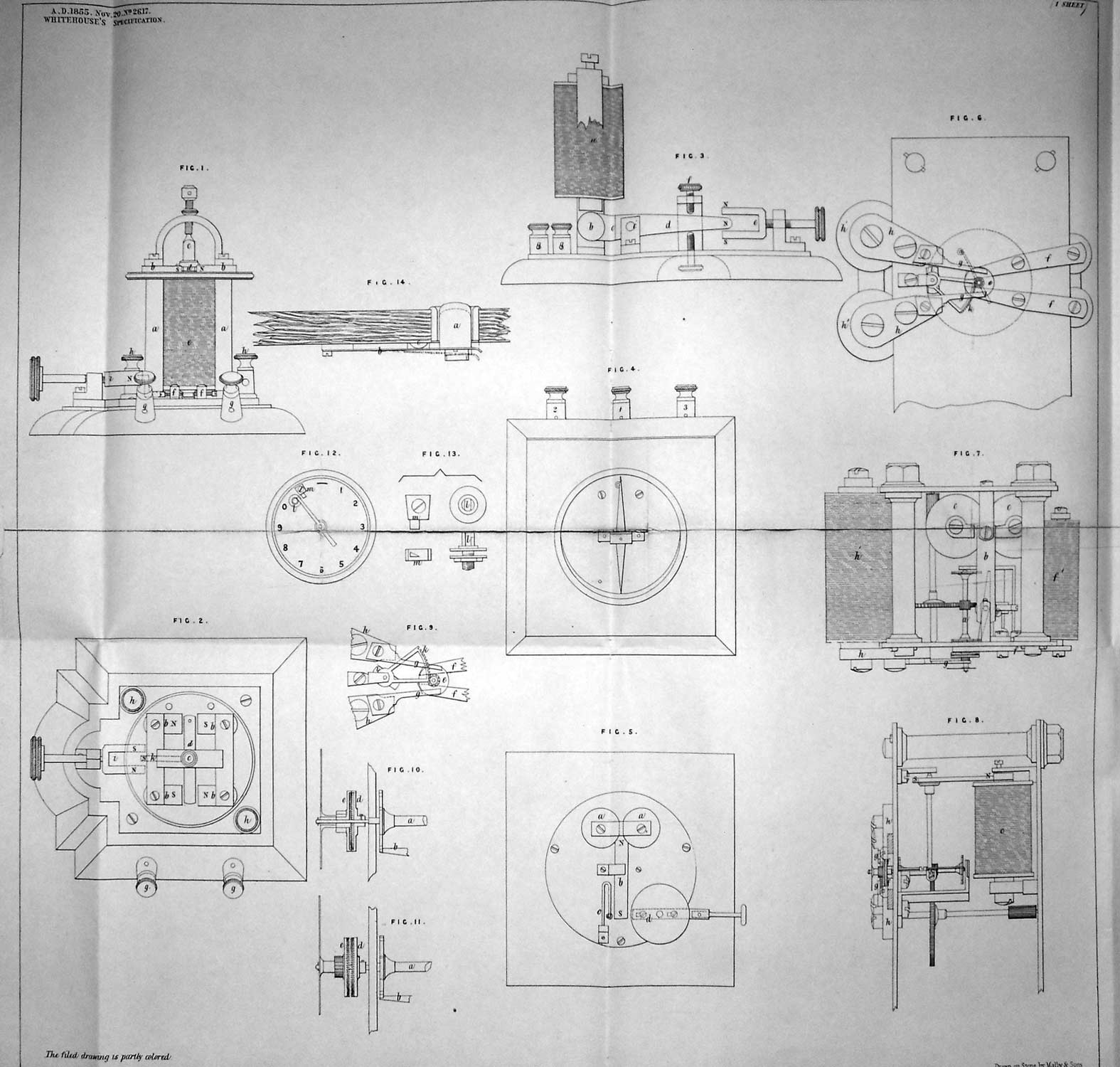
Fig. 1, side elevation of pillar relay; Fig. 2, a corresponding plan of the same, a, a, magnetic pillars; b, b, pole pieces of ditto, the relative polarities being marked by the letters, N and S, throughout the drawings; c, c, loose core of soft iron, working on pivots and carrying cross pieces of soft iron at each end; d, d, cross pieces; e, e, coil of wire surrounding the loose core; f, f, insulated banking screws for making contact with local battery; g, g, binding screws in connexion with ditto; h, h, binding screws in connexion with the wire of the coil; i, adjusting magnet; k, magnetized steel arm, fixed upon the loose core, c, by a brass collar. Fig. 3 represents a side elevation of a modification of a Morse relay, a, electro-magnet; b, piece of soft iron or keeper, placed near the poles of the electro-magnet, and fixed upon the lever, c; c, the lever carrying the keeper and working on a centre at c1; part of this lever at d is made of steel and is magnetized, e, adjusting magnet; f, insulated banking screws for contact; g, g, binding screws. Fig. 4 represents a top plan of my dead beat single needle instrument, and Fig. 5 is a corresponding plan of the under side of the same. a, a, electro-magnet; b, b, magnetic needle, one end of which is placed between the poles of the magnet; c and d, dumb stop and bell stop, either of which may be used at pleasure. 1, 2, and 3, binding screws, making connexion 1 between the local battery and the middle of the circuit of the electro-magnet; 2 and 3 between either limb of the electro-magnet separately, and the corresponding side contact of. the relay. Fig. 6 represents a front elevation of the releasing action, with the dial plate and hand (fig. 12) removed. Fig. 7 is a corresponding plan, and Fig. 8 a side elevation of the same. Figs. 9, 10, and 11 are parts of the reversing action, shown detached and in different positions; and Figs. 12 and 13 represent respectively the dial and hand, and the stops on the dial, a, a, axis of the pallet wheels of the escapement; b, magnetic needle, actuating the lever of the escapement; c, electro-magnets, producing the movements of the above, being itself called into action by the relay; d, brass disc, fixed upon the axis of the pallet wheels, the teeth of which disc take into the corresponding teeth of the moveable disc; e, the moveable disc, made of soft iron, playing loosely on its axis and carrying the hand of the instrument; f, f, prolonged poles of the holding magnet, f1, f1, whose action is to keep the teeth of the moveable disc, e, in gear with the other disc, d; g, g, prolonged poles of the releasing magnet, g1, whose action is to draw forward the moveable disc, e, and thus throw it out of gear, whilst the magnetism of the shorter and thicker part, h, of the poles takes effect upon a small piece of iron placed between them, and which by means of a toothed segment and pinion produces at the same instant the return of the disc, e, and hand to their original position; f, the small piece of iron fixed upon the axis of the toothed segment ; k, the toothed segment, taking into the teeth of the small pinion on the moveable disc. The position of this segment and the piece of iron, i, fixed upon its axis are shown in fig. 9, before the releasing action has taken place, and in fig. 6, immediately after the release. In the former figure, by the onward movement of the hand the small piece of iron, i, has been brought into an oblique position between the poles of the electro-magnet; and in the latter figure the attraction of the magnet has brought it into an axial position. Fig. 10 shows an enlarged sectional view of these parts in gear while under the influence of the holding magnet; and fig. 11 is an enlarged elevation of the same during the release. l, fig. 13, is the stop for the hand; it may be insulated, as shown, on one side, and made to give a contact on the other side to ring a bell when the attendant is absent; m is an incline, over which the hand passes on its release, and which serves to prevent recoil on the completion of the releasing action, or when the hand strikes the stop,l. Fig. 14 is a full-sized sectional detail of the stud employed for bringing into action the releasing movement, by diverting the local battery current from the holding to the releasing magnet. a is the stud; b, a spring in metallic connexion with local battery; c, contact for holding magnet; d, contact for releasing magnet. Having now described and particularly ascertained the nature of the said invention, and the manner in which the same is or may be used or carried into effect, I would observe, in conclusion, that I do not confine or restrict myself to the precise details or arrangements which I have had occasion to describe or refer to, as many variations may be made therefrom without deviating from the principles or main features of my said invention; but what I consider to be novel and original, and therefore claim as the invention secured to me by the hereinbefore in part recited letters patent, is,— First, the improved induction coils, as hereinbefore described; Second, the application and use of induction coils, in which the secondary current is generated by reversing the polarity of the iron by the primary current, as hereinbefore described for electro-telegraphic purposes, blasting, ordnance purposes, as well as for electro-chemical decomposition; Third, the improved forms of relays hereinbefore described, and the use of a small permanent horse-shoe magnet as a means of adjustment for relays; Fourth, the combination and arrangement described of a dead beat magnetic needle instrument, worked by a local battery in connexion with a relay, fitted to receive alternating currents, and the mode of exciting (by local battery and relay fitted to receive alternating currents) alternately the opposite limbs of an electro-magnet, so as to produce corresponding movements in a magnetic needle; Fifth, the adaptation to an ordinary step-by-step dial instrument of the peculiar releasing or retrograde movements, above described.—In witness, &c. Edward Orange Wildman Whitehouse. Return to the Wildman Whitehouse patents page |
|
Last revised: 3 June, 2010 |
|